Optimization Motion Planning with Tesseract and TrajOpt for Industrial Applications

Summary

Southwest Research Institute launched an internal R&D project to integrate the existing motion planner TrajOpt (Trajectory Optimization for Motion Planning) into ROS. TrajOpt was created at UC Berkeley as a software framework for generating robot trajectories by local optimization. The integration of TrajOpt necessitated new capabilities that spawned the creation of several new packages: tesseract and trajopt_ros. The tesseract package contains a new lightweight motion planning environment designed for industrial application, while the trajopt_ros package contains packages specific to TrajOpt. We will demonstrate how these tools complement existing planners, like OMPL or Descartes, to solve complex problems quickly and robustly.

Description

The original implementation of TrajOpt was developed using OpenRave for Kinematics and Bullet for contact checking. The first step was to replace OpenRave with MoveIt! Kinematics and second replace the collision environment with MoveIt!’s Collision environment. Early on in the process several limitations were found in both MoveIt!’s Kinematics and Collision environment.

TrajOpt requires the ability to calculate specific information about the robot not provided by MoveIt!, but it turns out KDL, which is one of the kinematics libraries used by MoveIt!, provides methods for obtaining the required information. This resulted in the development of a custom kinematics library built on KDL for both kinematic chains and non-kinematic chains. Secondly TrajOpt leverages specific characteristics of convex to convex contact checking to provide the minimum translation vector to move two objects out of collision. In the process of integrating with MoveIt!, it was determined that it did not provide detailed distance information. Also, after further evaluation it was found that MoveIt! does not support convex to convex collision checking requiring significant API changes across multiple repositories. Since the IR&D was time-sensitive, it was determined to not use MoveIt! and create a light-weight Motion Planning Environment (Tesseract).

The Tesseract environment was designed to support SwRI’s work in complex industrial motion planning applications where flexibility and modularity are key to adapting to new applications. Packages include:

  • tesseract_core – Contains platform agnostic interfaces and data structures to be used. tesseract_ros –ROS implementation of the interfaces identified in the tesseract_core package, currently leverages Orocos/KDL libraries.
  • tesseract_collision – ROS implementation of a Bullet collision library. It includes both continuous and discrete collision checking for convex-convex and convex-concave shapes.
  • tesseract_msgs – ROS message types used by Tesseract.
  • tesseract_rviz –ROS visualization plugins for Rviz for both the environment state and trajectories.
  • tesseract_monitoring – Provides tools for monitoring the active environment state and publishing contact information. This is useful if the robot is being controlled outside of ROS, but you want to make sure it does not collide with objects in the environment. Also includes the environment monitor, which is the main environment facilitating requests to add, remove, disable and enable collision objects, while publishing its current state to keep other ROS nodes updated.
  • tesseract_planning – Contains interface bridges between Tesseract Environment and motion planners OMPL and TrajOpt.

After the creation of Tesseract all necessary capabilities were available to finish the integration of TrajOpt into ROS. The new motion planner was evaluated against the following use case while minimizing joint velocity, acceleration and jerk cost along with collision avoidance cost:

  • Fully Constrained Cartesian Path
  • Semi-Constrained Cartesian Path
  • Free Space Path
  • Semi-Constrained Free Space Path
  • Free Space + Constrained Cartesian Path

Only a few of the above case will be discussed below. The first is a Semi-Constrained Free Space Path where a KUKA iiwa needs to plan around a sphere while maintaining tool orientation with the z-axis rotation free to rotate. Each step of the optimization is shown in Figure 1. Note that once the robot is out of collision the remaining iteration are spent minimize joint velocity, acceleration and jerk.

Figure <span style='font-size:11.0pt;line-height:
107%;font-family:"Calibri",sans-serif;mso-ascii-theme-font:minor-latin;
mso-fareast-font-family:Calibri;mso-fareast-theme-font:minor-latin;mso-hansi-theme-font:
minor-latin;mso-bidi-font-family:Ca…

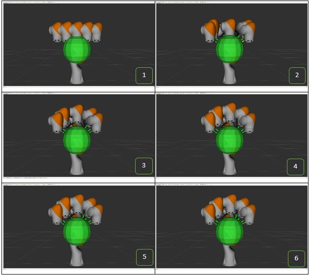
Figure 1 - KUKA iiwa (7 DOF) TrajOpt free space planning round sphere

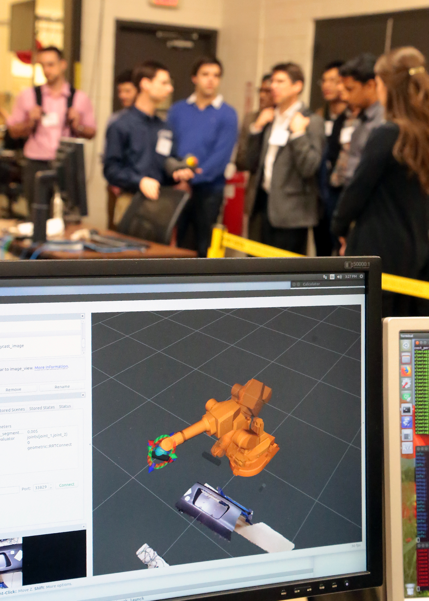
The next use case was a complex industrial application. It is an 8 DOF problem, where the robot picks up a seat off of a conveyor and loads the seat into a car. This is a very challenging task, given the amount of manipulation required to pass through the doorway and set the seat without colliding with the car structure. The final trajectory, found in 0.482 seconds using TrajOpt with continuous collision checking enabled, is shown in Figure 2.

Figure <span style='font-size:11.0pt;line-height:
107%;font-family:"Calibri",sans-serif;mso-ascii-theme-font:minor-latin;
mso-fareast-font-family:Calibri;mso-fareast-theme-font:minor-latin;mso-hansi-theme-font:
minor-latin;mso-bidi-font-family:Ca…

Figure 2 - TrajOpt Car Seat Installation Example

One significant advantage of the Tesseracts implementation of the Bullet Collision Library is the ability to perform continuous collision checking. An example demonstrating the use of continuous collision with TrajOpt is shown in Figure 3. Each red box represents a state in the trajectory with the green box being the collision object to avoid during planning. Under discrete collision checking each state would be found to be collision free even if the motion between states was not. With continuous collision checking enabled, it can be seen that a collision is detected when transitioning between state 2 and state 3 resulting in a collision-free trajectory.

Figure <span style='font-size:11.0pt;line-height:
107%;font-family:"Calibri",sans-serif;mso-ascii-theme-font:minor-latin;
mso-fareast-font-family:Calibri;mso-fareast-theme-font:minor-latin;mso-hansi-theme-font:
minor-latin;mso-bidi-font-family:Ca…

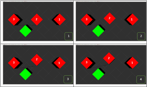
Figure 3 - Planar Box (2 DOF) TrajOpt free space planning with continuous collision checking

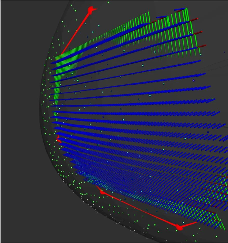
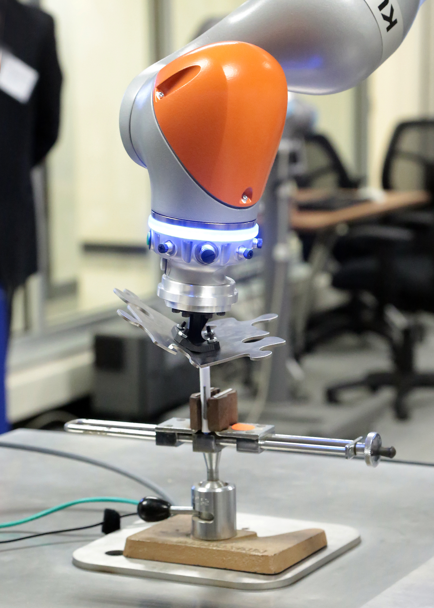
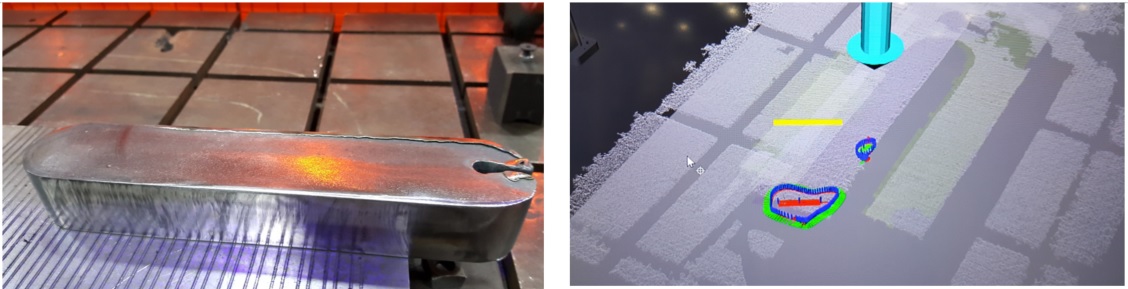
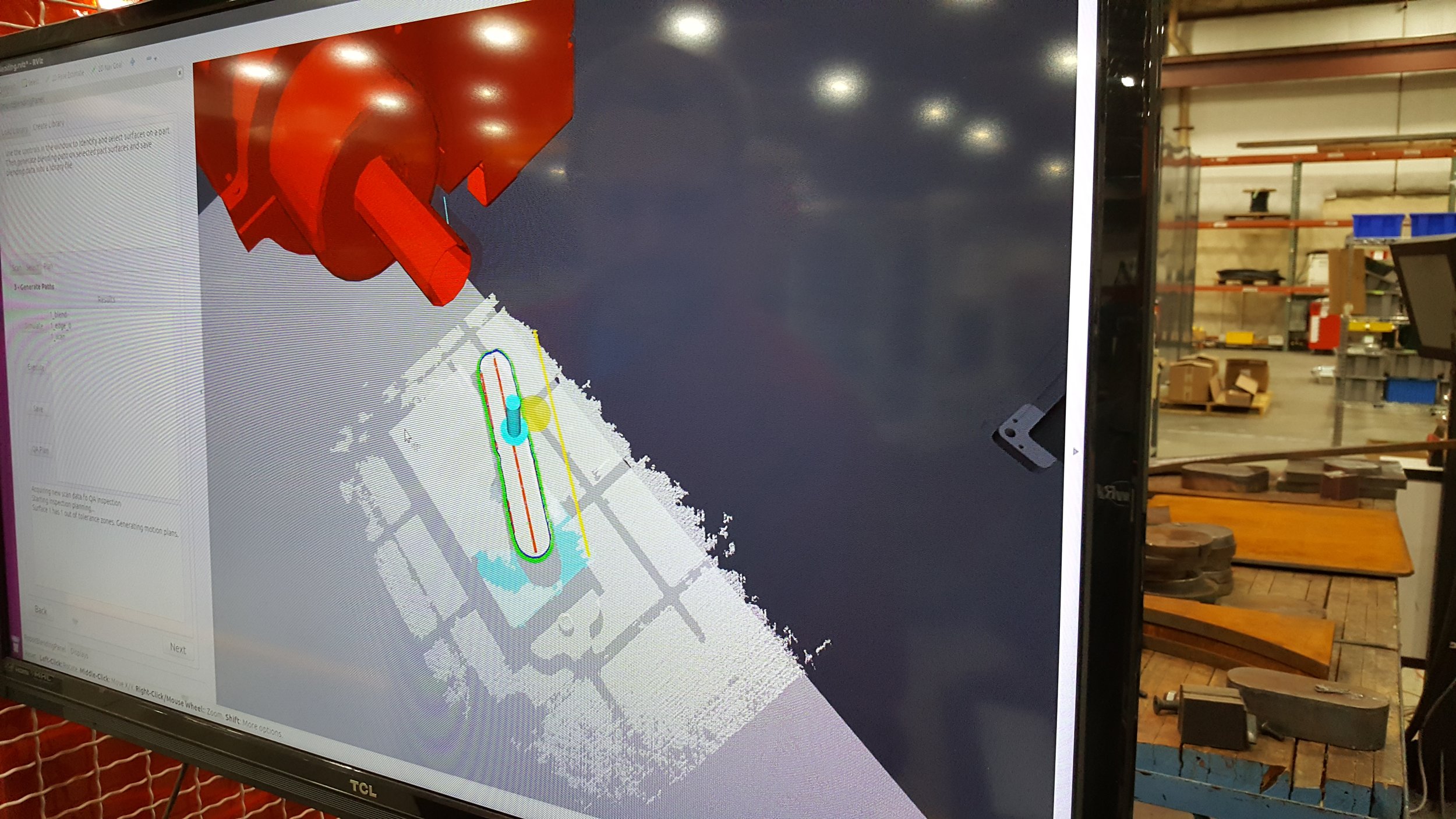
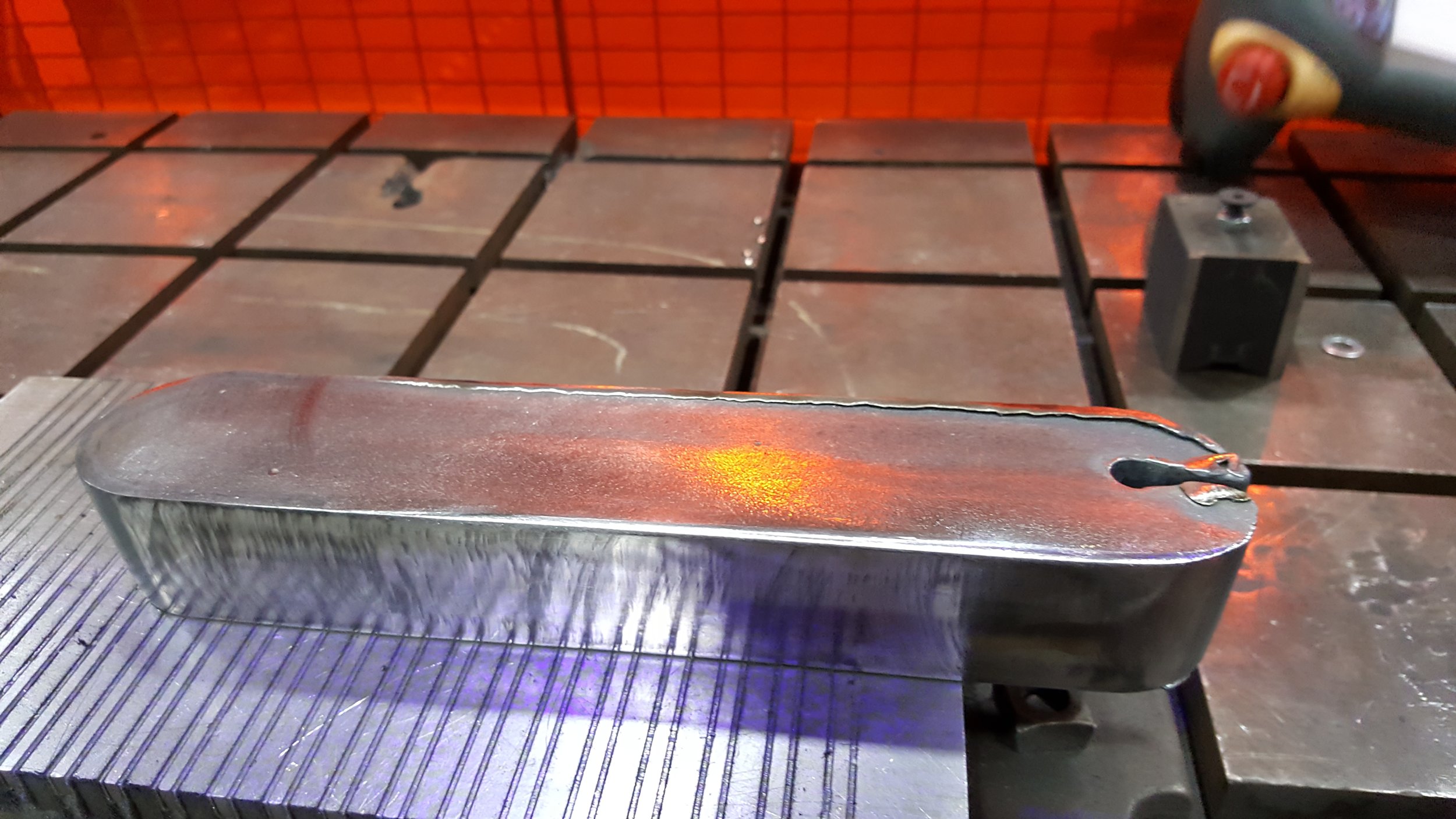
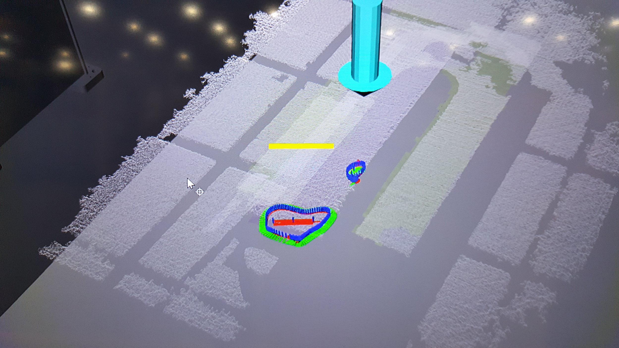
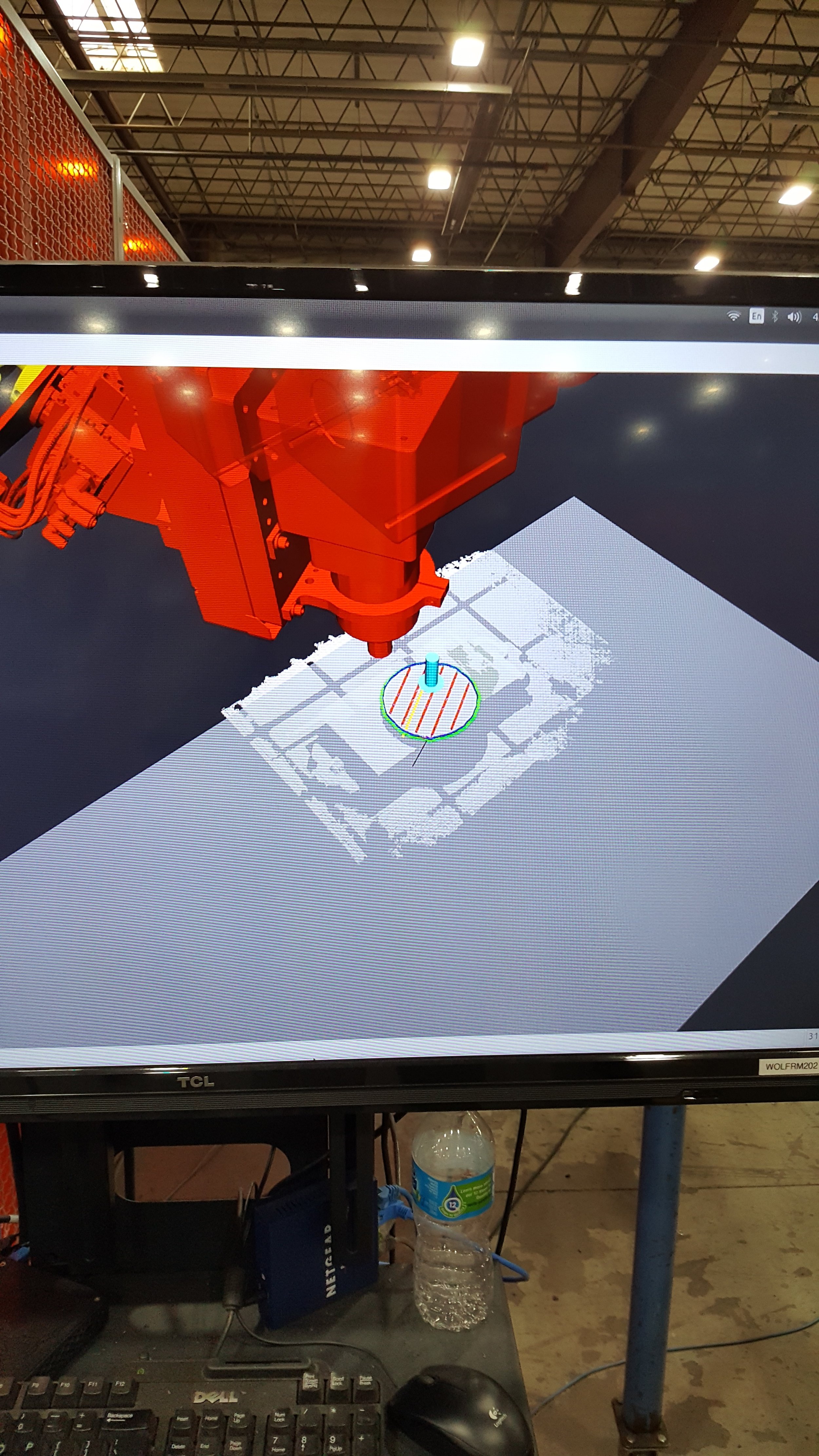
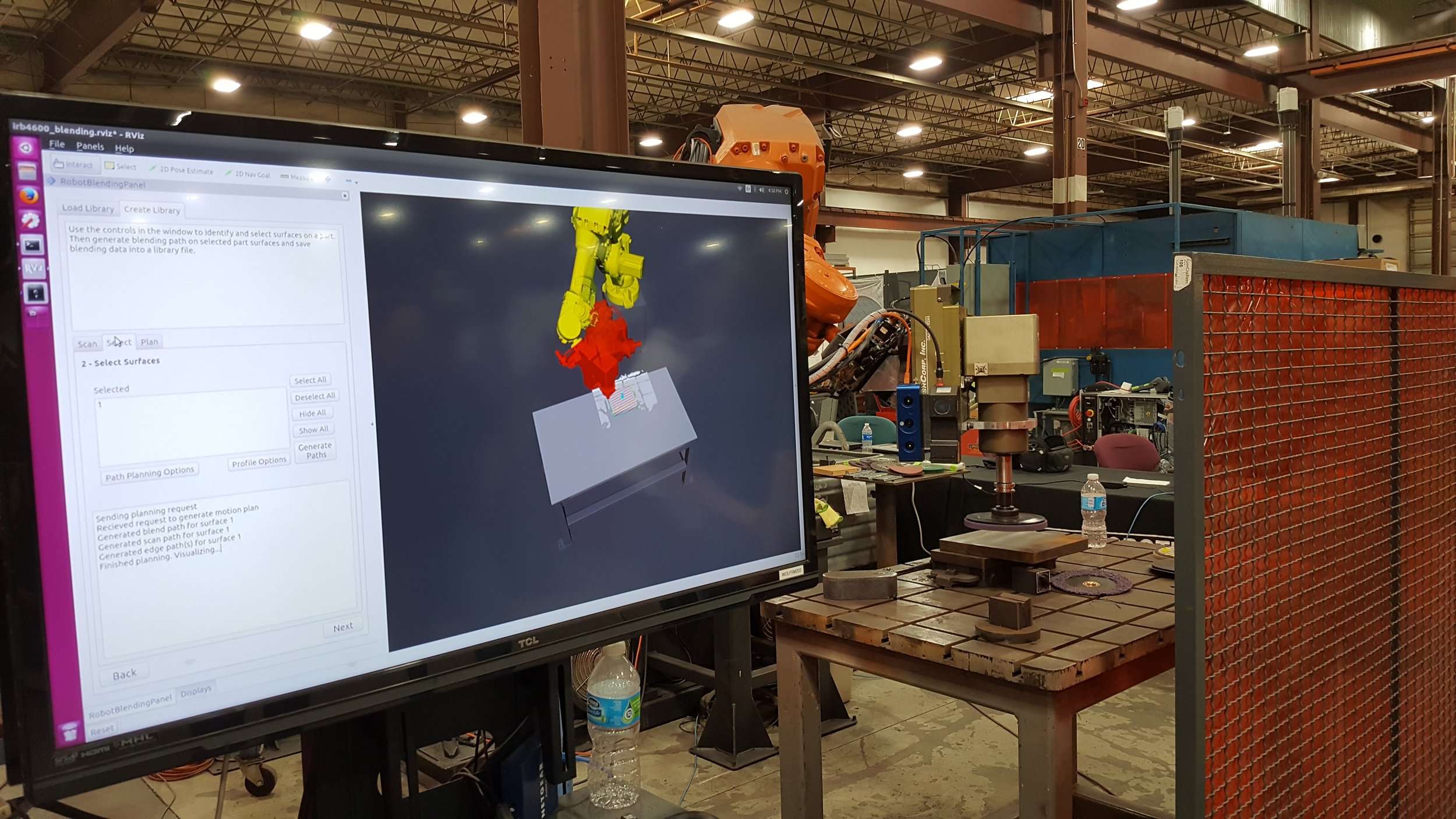
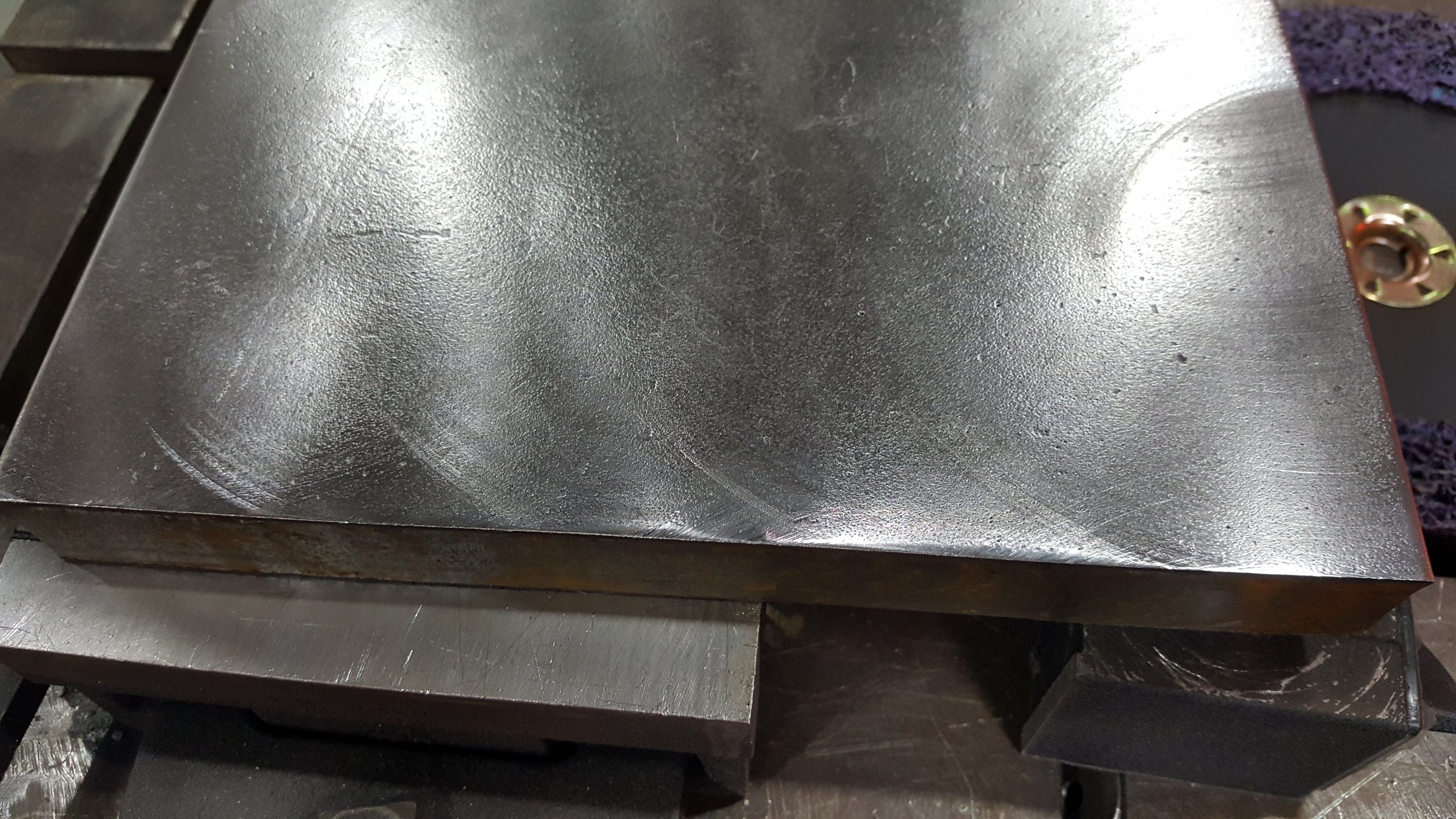
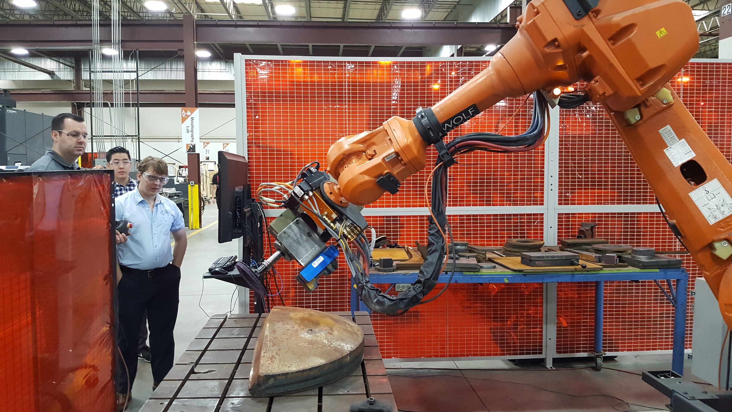
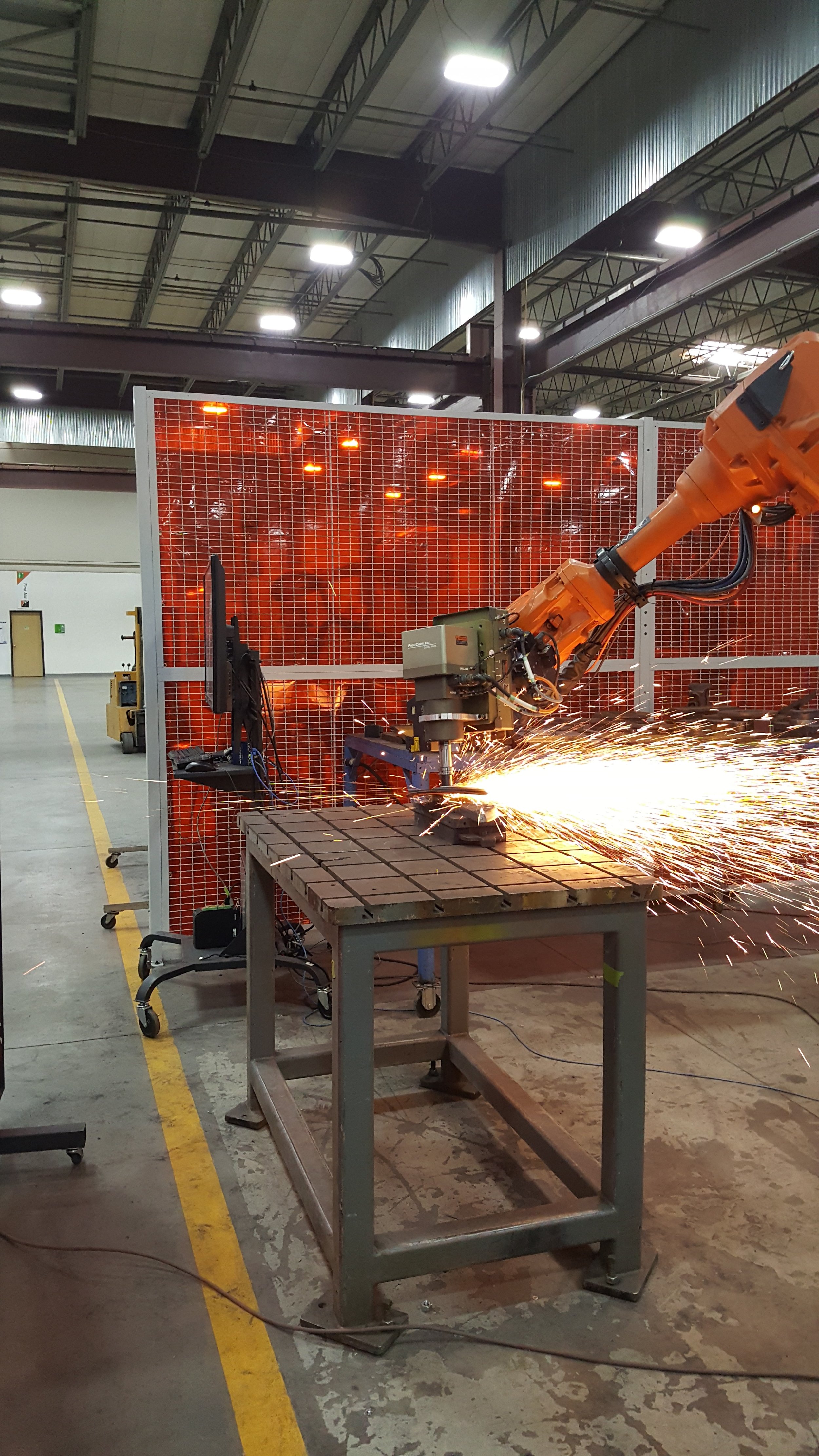
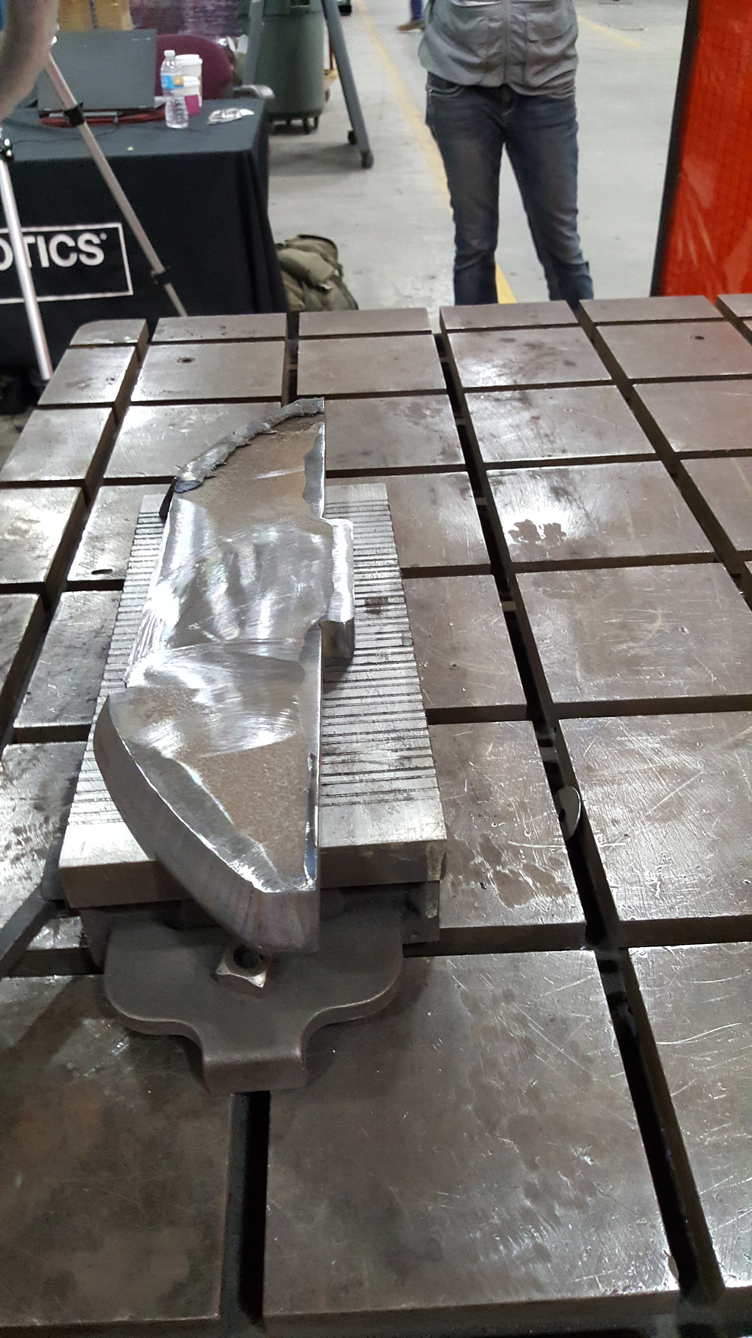
The remaining application to discuss is a complex Semi-Constrained Cartesian path with 437 poses each with 5 Degrees Of Freedom (DOF) fixed and the tool z-axis free to rotate. The application is performing a deburr operation on a complex puzzle piece shown in Figure 4. Also the problem includes a 7 DOF robot and a 2 DOF positioner for the spindle making it a non-fixed base kinematic chain. This requires the use of Tesseract’s joint kinematic model developed for this particular use case. The TrajOpt motion planner problem contains roughly 3,000 constraints and was able to solve in 4.4 seconds.

Figure <span style='font-size:11.0pt;line-height:
107%;font-family:"Calibri",sans-serif;mso-ascii-theme-font:minor-latin;
mso-fareast-font-family:Calibri;mso-fareast-theme-font:minor-latin;mso-hansi-theme-font:
minor-latin;mso-bidi-font-family:Ca…

Figure 4 – Semi-Constrained Cartesian Planning Problem

TrajOpt has shown itself capable of solving very difficult problems but, as an optimization, it can be sensitive to its initial conditions. This presentation will explore several strategies for seeding the solver, including the integration of sampling planners like OMPL and Descartes. These planners can coarsely and quickly sample the space of a problem to generate candidate solutions that can be refined by TrajOpt. If that should fail, a new robot configuration is selected from the sampled problem-space and the process repeated. For some problems this results in a planner finding a true global optimum.

References

  1. Tesseract Repository
  2. TrajOpt ROS Repository
  3. Examples (Tesseract and TrajOpt ROS)
  4. Videos

Driving Intelligent Inspection Processes for NDE/NDI

Nondestructive evaluation (NDE) techniques for parts and structures that are created from either forming processes or additively manufactured processes typically have had to be manually performed. Recent advances in scanning technologies and intelligent path planning tools, such as those available within ROS -Industrial, present a platform capable of performing multiple NDE processes in an intelligent fashion leveraging the Scan-N-Plan framework.

The Sensors Systems & Nondestructive Evaluation team within Southwest Research®, along with ROS-Industrial developers have conceived of a concept to enable a Scan-N-Plan approach to Nondestructive Inspection (NDI) thereby reducing the amount of inspection time by only performing detailed surface or volumetric inspections where mandated by an initial higher level screening.

The Sensors Systems & Nondestructive Evaluation team has developed a unique technology within their portfolio that performs full volumetric inspection using a guided wave technique that leverages an omni-directional probe. The concept would be to perform a macro-level scan leveraging the MsT360 Guided Wave Sensor, analyzing the output and for indications, or areas of interest, drive low level inspection. A sample output from this stationary sensor can be seen below. This output can then be leveraged to generate process paths for follow on inspections such as Eddy Current (EC) or Ultrasonic Testing (UT), only in the areas of interest. This provides the full volumetric inspection output, but reduces the time spent doing a 100 percent surface scan with higher resolution traditional UT. This improves solution velocity as well as reduces post-processing clean up.

Based on experience with the MsT360 follow-on low level inspection techniques can be selected based on the characterized potential defect. The system would then Plan trajectories based on this scan for each process, including the stand-off or contact forces and trajectories mandated by the process. A map could be visualized and colored to aid the operator in understanding which regions will be inspected by which NDE process. In the below example for instance, a process would be planned for the area identified with the 35% wall area, or where weld 1 and 2 are located, as opposed to UT or EC of the entire volume or surface respectively.

Scan output.JPG

Sample output from MsT360

A sample workflow for this type of operation would be as such: • Assembly or Piece within a robotic system is ready for NDE Assessment • Locate MsT360 Guided Wave Sensor (Manually or Robotically) • Perform macro volumetric inspection • Analyze output • For areas of concern plan trajectories for each process type (EC or UT) and execute inspection in the areas of interest • Tool Change • Perform inspection • Tool Change if required • Clean • Generate Report; either unload or launch a repair process

The flexibility inherent to this design and the capability included enable processing of piece-parts, such as forms, as well as fabricated structures. The macro scan and detailed path planning approach is more efficient for when it is not inherently value added to inspect an entire volume or surface area.

Planned Region.JPG

As can be seen in the above image, specific regions can be highlighted based on an output such as described earlier, or these can be user adjusted based on a response from a developed GUI. These trajectories can be planned for all the processes of interest, in this case UT and EC, with their requirements relative to process execution included. Leveraging the flexibility of the Scan-N-Plan framework it is easy to see how NDE processes can either be included into a multi-process cell, or just automated in a manner that effectively applies them where required, or where that detailed scrutiny is most beneficial. Furthermore, this can be augmented with visual imaging to allow for assessment of human readable details , or human generated markings to drive further process planning and inspection. For future consideration as well are several visual NDE techniques for surface inspection that could be incorporated, such as dye penetrant, magnetic particle, pulsed thermography, etc.

Human Markings.JPG

Example of Identification and Tool Path Plans for a Human Generated Indication

As advances in both inspection technologies and automation move forward there lie the opportunities to more tightly couple these processes, and optimize their effectiveness in the areas of greatest need. This enables more efficient utilization while optimizing cost and throughput, as well as reducing non-value-added steps that currently come with many of the NDE techniques. Moving forward we hope to see more opportunities for integrated quality evaluation within automation applications, enabling further optimization of manufacturing value streams. For more information about SwRI’s NDE solutions please visit: https://www.swri.org/industries/sensors-systems-nondestructive-evaluation-nde

A brief report from the ROS-Industrial EU Spring workshop

Thanks to the participation of several members of the ROS-Industrial community in Europe and of new participants interested in knowing more on the topic, we are happy to report on a successful ROS-Industrial EU Spring’18 Workshop at Fraunhofer IPA.

During the two days of May 28-29, organizations within the ROS-Industrial consortium had the opportunity to present their current development projects to an audience of technical experts.

Erle Robotics, represented by Irati Zamalloa, presented the concept of a common interface for the description of robot modules and hardware sub-components allowing their reusability, composability and interoperability. The project is already publicly available as a ROS2.0 implementation. During the ensuing Q&A, feedback from participants pointed to the possibility of integrating such effort with a MDE approach, where the information could be semantically annotated and verified. Further feedback is welcome, with a github repository setup for the purpose.

DSC_0002.JPG

The second workshop session focused on ways to make ROS-based systems and PLCs interoperable. Sebastian Friedl from the University of Stuttgart gave an introduction to the OPC-UA architecture and the improvements that his institution is making on this open source implementation of the protocol. He also presented the ROS <-> OPC-UA gateway that is under development within the SeRoNet project.

On a similar topic, Tiago Pinto from INESC TEC continued the session showing how his team approaches communication between CODESYS and ROS systems. The implemented wrapper is already being used for practical application within the project ScalABLE 4.0, with source code scheduled for public release in August.

DSC_0004.JPG

Wrapping up the topic, Ludovic Delval from Faunhofer IPA presented a survey of the existing ROS drivers implementations supporting different fieldbus protocols. The detailed overview was appreciated by the participants and is available as reference here.

As part of the efforts of the ROSIN project to make ROS-Industrial better and business-friendlier, partners of the consortia joined for the second day of the workshop to show the tools developed for the quality assurance on the ROS software development. Jonathan Hechtbauer from Fraunhofer IPA and Anthony Remazeilles from Tecnalia gave an update of the software efforts like the improvements on the quality badge, the rosinstall time machine tool, and a generator for ROS packages. Preliminary code is available at the github organization of the project.

Concluding the event, the ROSIN coordinator Carlos Hernández Corbato informed the audience about the opportunities for ROSIN Focused Technical Projects. A grant up to 100K to fund your software development is available to institutions with a legal seat in the EU and associated countries. The application process is explained in detail at the project page.

Given the request from interested parties who could not join us in Stuttgart, we made the content and slides of this workshop publicly available under the following link.

We look forward to a second edition of the workshop in the fall!

New Release of the ROS Qt Creator Plug-in

We are pleased to announce the release of the ROS Qt Creator Plug-in for Qt Creator 4.5.1 on Trusty and Xenial. The ROS Qt Creator Plug-in creates a centralized location for ROS tools to increase efficiency and simplify tasks.

Highlights:

  • The installation has changed from using a debian installation method to using the Qt Installer framework. This change is to facilitate tighter integration with existing ROS capabilities and libraries within Qt Creator.
image1.png
  • A set of new video tutorials were contributed by Nathan George broken down into five parts:
    • Installation
    • Import, Build, and Run Settings
    • Create Hello World C++
    • Building Hello World
    • Indexing, Auto Complete and Code Style
  • Updated wiki using Sphinx and GitHub Pages to provide a richer wiki.
  • In an effort to make it simpler when using the dugger within Qt Creator for ROS an “Attach to unstarted process” run step was created as shown below.
image2a.png
  • A set of existing ROS templates were added to simplify adding ROS specific files within Qt Creator.
image3.png
  • Additional changes
    • Show hidden files/folder like .clang-format and .rosinstall.
    • Support for catkin tools partial build capabilities.

First ROS-Industrial Consortium Americas Training for 2018

The ROS-Industrial Consortium Americas recently completed another successful ROS-I training event April 10-12 at Southwest Research Institute. We had 11 people from a variety of industries complete the Basic and Advanced training material, which covers a variety of topics from creating a ROS node, publishers, subscribers, and using the ROS parameter server. The Advanced training material covered motion planning using Stomp and Descartes, as well as creating a computer vision application using the Point Cloud Library (PCL).

On Day 1, the Basic and Advance track groups met separately, but were merged together the remaining days. The training material was cumulative so that by the end of Day 2, participants had a working ROS project that could move a robot to a simulated box location. On Day 3, everyone got to try their hand at a more challenging vision or path planning project. Many were able to complete the challenge and execute it on one of the available robots.

20180412_085406.jpg

Attendees also got a short tour of SwRI's lab space that included hardware for application testing and development. By request, a subset of attendees requested a breakout session where they were able to see a side-by-side comparison of some of the 3D depth sensors available, as well as a new surface reconstruction technique, taking advantage of the proximity of the lab space and the development hardware available.

20180412_084254.jpg
20180412_084818.jpg

Thanks to everyone who came and helped make this event great! If you have questions about ROS-Industrial training, please feel free to contact us. Keep an eye out for the next ROS-Industrial Consortium Americas event at the Events page!

Leveraging Scan-N-Plan for Additive Manufacturing

Implementing Additive Manufacturing (AM) principles with a collaborative twist is still an unexplored area of manufacturing. Traditional AM typically involves step motors moving a printing head, or a laser bonding a material to itself. More advanced solutions have even gone to mounting print heads as robotic end effectors to gain a larger print volume. A ROS framework has already been developed in this space, though additional features are always of interest.

Often when a part is damaged it is either thrown out or repaired with direct labor. What if there was a way for autonomous blending part repair with AM? Assuming a known CAD model, a Scan-N-Plan AM solution could bring new life to previously scrapped parts. The method proposed here involves bringing in a damaged part, doing a laser scan and determine which elements of the part need repair.

Laser scans produce good resolution of parts and is largely insensitive to material and surface quality though some cases may require several scans to achieve high resolution. A pre-scan process can easily assume this role to reduce print downtime. The scan in the image below was done on a FARO arm. As can be seen, in the image below, the quality is excellent. The file exports a point cloud that can be imported into the ROS framework. Similarly, a non-contact structured light sensor could provide the output as seen below, whereby subsequent process planning could be driven.

Crack.jpg

Once the file is scanned, the part is then checked against a master CAD file. The deviation of the point clouds indicates where the flaw exists. The point cloud is then converted to a YAML file and the path is generated. Locating the part between scan and print head is done using 3 known touch off points or a non-contact form of localization. The material deposition process is then free to take place. For cases such as the above example where prep-work is required to enable material deposition, a cutting or grinding tool can be process planned and executed as well to create a suitable prepared region for material deposition to occur.

Additive Value Stream Reman.png

In remanufacturing use cases, specifically where the variation is high due to the unknown state of the provided material, a more efficient workflow with higher return and repurposing of field return material is possible. The leverage of a ROS-based framework in a distributed manner could enable common intelligence being applied over a range of assets residing at multiple sites, making process control more uniform wherever the operation takes place. Furthermore, as in the case in remanufacturing, as opposed to additive processing (building up) a complete part, leveraging the Scan-N-Plan framework enables optimization of applying only where the additive process delivers the most value in the broader context of the value stream and cost of both incoming materials and the processing itself. An example of this would be the replacement of a linkage forging on a structure with an additive deposit, where the remaining structure is fabricated plate material, the additive can be optimized to both manage load (print direction and properties), while optimizing costs where commodities do the job and are readily available at favorable costs.

Issues that could arise with this process include interference with the print head with the part (oddly shaped flange interfering with a robot wrist independent of the print head) and cable management for certain types of deposition processes. Though material waste is minimal with advances in additive near-net processing, there is the cost and maintenance of the media and encompassing all of the tools that need to be accessible to the manipulator, from the QA assessment, material prep/finish/surface treatments, and of course the AM process itself. Underside printing would be a second print unless an auxiliary positioner is implemented, such as in some of the more recent hybrid additive/subtractive platforms.

Physical attributes of a repair part are untested based on metallurgical properties. Part repair is still a fledging industry of research, though there have been recent advances in aerospace remanufacturing. Cohen has done some work with tissue engineering and still uses a 3-axis step motor . Great advances still stand to be made in this research area, however a number of tools exist to create an agile process leveraging the benefits of additive and approaches like Scan-N-Plan.

ROS-Industrial Americas 2018 Annual Meeting Review

The ROS-Industrial Consortium Americas (RICA) held its 2018 Annual Meeting in San Antonio, on the campus of Southwest Research Institute (SwRI) on March 7th and 8th, 2018. This was a two-day event, with the 7th open to the public, including tours and demonstrations, followed by Consortium Members meeting on the 8th with a road-mapping exercise and project idea brainstorming.

This was the first time that RICA held the event over two full days. Also, this was the most well attended event, topping out over 80 people on the 7th. There were talks spanning from the more strategic/visionary to the technical with regards to open-source robotics application development. This provides an excellent cross-section of the technical development community and organization decision makers to share ideas and cross-pollinate taking back what they learned to their organizations.

The morning of the 7th featured:

  • SwRI Introduction - Paul Evans - SwRI
  • ROS-I Consortium/Introduction - Matt Robinson - SwRI
  • Manufacturing in Mixed Reality - Dr. Aditya Das - UTARI
  • Discussion on the Design of a Multiuse Workcell and Incorporation of the Descartes Package - Christina Petlowany - UT Austin Nuclear Robotics Group
  • Integrating ROS into NASA Space Exploration Missions - Dustin Gooding - NASA

The talks touched on a mix of how humans can interact with the technological solutions and also the need for solutions that can work within environments originally designed for people. The common thread is enabling humans and robots to work more efficiently within the same spaces, and leveraging the same tools.

Rick Meyers of the ARM Institute & Air Force Research Laboratory, during the lunchtime keynote, discussed the vision and motivations of Air Force ManTech to drive advancements in automation and robotics in the manufacturing environment. This tied into the motivation of the Advanced Automation for Agile Aerospace Applications (A5) program, and how ROS ties into the realization of the Air Force ManTech vision.

The tours and demonstrations included many different applications, all with either ROS/ROS-Industrial element, though in some cases complimentary. ADLINK Neuron focused on coordinated mobile robots and a means to assist their industrial partners to easily transition to the ROS2 environment and provide consulting services for DDS implementation and ROS-related algorithm development.

KEBA demonstrated their new ROS RMI interface integrated into their controller, while UTARI demonstrated Manufacturing in Mixed Reality implemented through the Microsoft HoloLens, allowing users to fuse process guidelines, real-time inspection data, and cross reference information to determine adaptive measures and project outcomes.

SwRI and the ROS-I team demonstrated an example of merging SwRI’s Human Performance Initiative’s Markerless Motion Capture combined with path planning to retrieve an object from an open grasp. SwRI’s Applied Sensing Department showcased their Class 8 truck enabling all attendees to go for a ride, while gaining insights to the vehicle’s capabilities. The ROS-I team at SwRI also presented Robotic Blending Milestone 4, Intelligent Part Reconstruction, with TSDF implementation, and Trajopt, a newly fully-integrated into ROS sequential convex optimizer. The UT Austin Nuclear Robotics Group demonstrated their improved situational awareness for mobile manipulation on their Husky platform where users could “drive” the system to pick up a presented object.

Finally, the SwRI team presented and demonstrated the A5 platform, which is a mobile manipulation platform designed to perform numerous processes on large aircraft in an unstructured setting. The process demonstrated was sanding of a test panel overhead. Overviews of the localization and planning on the visualization were included.

Talks for the afternoon centered around OEM and Integration service providers, and included:

  • ADLINK Neuron: An industrial oriented ROS2-based platform - Hao-Chih Lin - ADLINK
  • Unique ROS Combination with Safety and PLC - Thomas Linde - KEBA
  • Leveraging ROS-Industrial to Deliver Customer Value - Joe Zoghzoghy - Bastian Solutions

This set of talks brought home innovations by the OEM and service provider communities. Bastian Solutions’ story of concept via working with the ROS-Industrial team, through pilot and into production, demonstrated a real value proposition for mobile solution, and broader ROS-enabled, development for the integrator community.

The morning of the 8th featured:

  • RIC-Americas Highlights and Upcoming Events - Matt Robinson & Levi Armstrong - SwRI
  • RIC-Europe Highlights & ROSiN Update - Mirko Bordignon - Fraunhofer IPA
  • ROS-Industrial Lessons from Bootstrapping in Asia Pacific - Min Ling Chan - ARTC
  • ROS2 is Here - Dirk Thomas - Open Robotics
  • ARM Institute Introduction & Update - Bob Grabowski - ARM Institute
  • Windows IoT & Robotics - Lou Amadio - Microsoft

Matt Robinson covered strategic initiatives for the Consortium followed by Levi Armstrong covering RICA technical developments, including TrajOpt and Intelligent Part Reconstruction, Noether, PCL Afront Mesher, and Qt Creator updates and upcoming release.

Mirko Bordignon highlighted for the Americas audience what is happening around the ROSIN initiative, driving awareness, and furthering the global nature of ROS-I. Min Ling Chan shared progress within the Asia-Pacific region and the progress and status of the Pack ML Focused Technical Project, which has a Phase 2 launch coming soon.

Dirk Thomas of Open Robotics presented the latest on ROS2, and for the first time we were happy to welcome Bob Grabowski of the ARM Institute. The ARM Institute is the newest DoD Manufacturing Innovation Institute, and this is the first Annual Meeting since the Institute’s launch. Synergies between the ARM Institute and ROS-I will be important to monitor moving forward.

The morning session concluded when the Windows IoT and Azure teams were represented respectively by Lou Amadio and Ryan Pedersen, presenting their current strategy for ROS support and their plans moving forward, particularly for ROS2.

The featured keynote was presented by Dr. Phil Freeman of Boeing, “Why Boeing is Using ROS-Industrial.” Phil offered great insights to the value of ROS-Industrial for Boeing, and what it has enabled for their operations in the context of the challenges Boeing faces. The talk featured example applications and conveyed the message that within the robotics space we truly are at a tipping point with regards to capability and accessibility.

A road-mapping session was then conducted, focusing on problems to solve. The idea is to tie problems to projects and then identify the capabilities that need to be developed to meet certain prioritized problems. The problem focus areas were Human Capability, Quality Processes and Execution, Flexibility/Agility, and Strategy/Alignment. Common themes were: standard interfaces, documentation, ROS2 for Industrial applications, ownership and community engagement, simpler recovery means, and real-time diagnostics.

The afternoon speaker session touched on technologies that seek to enable richer and more reliable networking and data sharing/management through the application development/implementation process, and across the value stream:

Now that the dust has settled, these are some observations from this seat:

  1. ROS-Industrial is a big tent, and is truly global. Each Consortium needs to optimize how it works within their region to meet their member needs and optimally leverage resources available to them.
  2. As regional resources are optimized, the other consortia need to monitor developments, share information and ensure that all within the broader ROS-I organization are aware what is in-flight, what development activities are happening where, to reduce/eliminate redundant efforts.
  3. ROS2 is here, but there is work to do. It will be important to monitor developments and foster awareness to enable developers, solution providers, and end users to leverage ROS2 capability to complement their end solutions when and where appropriate.
  4. There are a number of innovators, solution providers, and end users realizing value proposition on ROS/ROS-Industrial deployments TODAY, and in some cases for some time. Let’s socialize and share their success stories.
  5. Foster both membership engagement and community engagement in the vision and execution of the vision for ROS-Industrial. We are excited to both enable start-ups to engage, but also improve how we leverage our University partners. Through effective projects, sponsorships, or roles within the ROS-I organizational structure, these all help foster a sense of community and subsequent ownership.
  6. There is an inflection point or tipping point, and for advanced robotics this seems to be an appropriate time. The idea also, that ROS can span beyond just the robotic processes, but do more to enable more intelligent processing via leveraging IoT, enable leverage of advanced technologies for further end user value seems to be gaining steam.
  7. We advance ROS-Industrial together. Engage, participate, communicate, and we succeed together.

As always, we are looking forward to feedback on the event and how to improve this event and events moving forward. We are looking forward to bringing back the online quarterly membership meetings, so keep an eye on that, as coordination and the invites are hosted on a rotational basis by the three Consortium managers. ROS-Industrial is an open-source project, and with that we seek to be open, and a be that forum for sharing ideas, and solving problems for industry in the 21st century.

Public day presentations can be found on the Event Page within the agenda after each speaker line item. Member day presentations are included behind the member portal, and are available for download.

Thanks for your support of open-source automation for industry!

Human Performance Researchers Pair ROS-I with Markerless Mocap

The ROS-Industrial team recently collaborated with Southwest Research Institute’s Human Performance Initiative to develop a demonstration robot for an exhibit at Arizona State University. The idea was to leverage work around their Markerless Motion Capture technology, which enables precise, 3-D capture of biomechanical movement, and merge it with the path-planning capability inherent to open-source ROS/ROS-Industrial. The demonstration would recognize a hand, and a specific open gesture of a user and this would then queue the robotic system to retrieve a part from the hand. Though this first iteration only relied on recognizing the object, the training for hand recognition is still of interest and not far off.

Set Up and Final Demonstration Testing at Arizona State University

Set Up and Final Demonstration Testing at Arizona State University

The Human Performance Initiative (HPI) is advancing the motion capture space by improving the performance of motion capture without the need to wear cumbersome suits with the well-known “ping pong balls” attached, and a complex array of cameras. The latest developments by the HPI team involve leveraging expertise in neural networks, sensor fusion, and biomechanics to realize markerless motion capture that can be leveraged, essentially on the fly focusing initially on biomedical, sports science, and animation applications.

In the manufacturing research space, there has been broad interest around understanding what people are doing in the work space. This is mostly in the context of: effective use of space, optimizing ergonomics, recording traffic patterns, predicting or enabling improved safety by understanding people movement, and quantifying the interaction between value stream efficiency and human interaction and movement.

The long-term vision here would be to combine richer, dynamic biomechanical monitoring to enable gesture recognition. In this context, a robot can understand when to interact, and possibly respond based on gesture or human queue. An open palm means “take” or “place” next tool for instance, or a hybrid of verbal and physical combined on the fly by the system. This type of collaboration today is not possible due to limitations in the perception technologies in the context of human-to-human variation, both in structure (size and shape) and how humans specifically execute a gesture, such as indicating they are ready for a robotic hand to take something from them, and the anticipation of what the human may do next.

In another future state you can imagine the optimal coordination of both mobile robots and humans in a complex orchestration in a high-mix manufacturing environment. Adjusting the process and the tasking of the robots even based on perceived fatigue of the human team members. Continuous value stream, or whole plant optimization combined with this type of human performance monitoring and feedback from the automated partners enable a new paradigm for true manufacturing optimization. There are many pieces coming to maturity to enable this vision, but they need to be brought together to see what is possible.

Markerless Motion Capture recognizing "Open Hand" &amp; launching path planning to retrieve part from recent 2018 ROS-I Consortium Americas Annual Meeting.

Markerless Motion Capture recognizing "Open Hand" & launching path planning to retrieve part from recent 2018 ROS-I Consortium Americas Annual Meeting.

The idea of a “robot assistant” that can be an active participant in helping a worker to complete a task is still a long way off, but demonstrations such as these offer a meaningful proof-of-concept test bed, to help aid in the roadmap to realize some incremental improvement. Cross-disciplinary collaborations such as ROS-Industrial and the Human Performance Initiative can enable the ability to see what can be done by leveraging the work from each team, each with their own discrete objectives, to realize an entirely new capability set. Here at ROS-Industrial we welcome and advocate for these proof-of-concept type evaluations, and seek to provide the means to enable them.

Visit the Human Performance Solutions web page for more on that team’s capabilities and offerings, and follow them on Twitter @SwRIHP.

Part 1, Updates and New Strategic Initiatives for the ROS-Industrial Consortium Americas

Recently ROS-Industrial Consortium Americas Leadership, along with review, and consultation, with the global ROS-Industrial leadership, presented to the Americas Consortium Advisory Council a number of proposed changes to the agreement, this post is a summary of the most meaningful changes and initiatives.

Read More

ROS-Industrial Migration to Discourse

Today, February 14th, we notified the ROS-I users Google Group, about an upcoming transition to Discourse on March 1. I have included the letter below that was provided to the Google Group members. We are excited to be part of the ecosystem over at Discourse and hope that it drives improved collaboration, synergy, and interaction with the broader ROS Community.

We look forward to this transition, but of course with any change, there can be problems. Please feel free to comment below, or reach out directly if you have questions and/or concerns.

Discourse.JPG

“In recent years there has been a migration, related to ROS/ROS-related discussions, Q&A, and collaboration to ROS Discourse (discourse.ros.org). At ROS-Industrial we see this year as the time to move over to Discourse as well, and retire the ROS-I Google Group, swri-ros-pkg-dev. This obviously does not come without some consideration and a migration plan. The target date for the transition is March 1. The content that is currently within the forum over at the Google Group will be kept available for reference, as read-only, and inquiries to swri-ros-pkg will be met with an automatic reply to direct inquiries to the ROS-Industrial Discourse category.

For users the move to Discourse should be quite convenient and efficient. Accounts from GitHub, or Google, may be used, so no new accounts will be needed in those cases.

We hope that this change is welcomed as it drives synergy with the broader ROS community, and allows for a true “one stop” in discussion and collaboration on all things ROS. To start there will be an ‘ROS-Industrial’ category, with subcategories developed when traffic merits the creation of subcategories.

We would like to thank our friends over at Open Robotics for helping us out with this change.”

Announcing ROS#

This is a guest blog post by Martin Bischoff on behalf of his employer Siemens AG. Thanks to Martin for the update, and to Siemens for its generous support to the ROS-Industrial Consortium!


We are happy to announce that we published ROS# on github.com/siemens/ros-sharp!

RosSharpLogo.png
 

...is a set of software libraries and tools in C# for communicating with ROS from .NET applications, in particular Unity.

ROS# consists of:

  • RosBridgeClient, a .NET API to ROS using rosbridge_suite on the ROS side.
  • UrdfImporter, a URDF file parser for .NET applications.
  • RosSharp.unitypackage, a Unity Asset package providing Unity-specific extensions to RosBridgeClient and UrdfImporter.

ROS# helps you to:

  • Communicate with ROS from within your Windows app: subscribe and publish topics, call and advertize services, set and get parameters and use all features provided by rosbridge_suite.
 
CodeExample.png
 
  • Import your robot's URDF model as a Gameobject in Unity3D. Import the data either directly from the ROS system using the robot_description service or via a URDF file that you copied into your Unity Asset folder.

(click on the images for videos)


  • Control your real Robot via Unity3D.
 
 
  • Visualize your Robot's actual state and sensor Data in Unity3D.
 
 
  • Simulate your robot in Unity3D with the data provided by the URDF and without using a connection to ROS. Beside visual components as meshes and textures, also Joint parameters and masses, CoMs, Inertia and Collider specifications of Rigidbodies are imported.
 
 
  • And much more! ROS# is useful for a wide variety of applications. Think about Machine Learning, Human-Machine Interaction, Tele-Engineering, Virtual Prototyping, Robot Fleet Operation, Gaming and Entertainment!

Got Interested?

Please do not hesitate to try it out yourself and to get in touch with us! We are very interested in your feedback, applications, improvement suggestions, and contributions!

ROS# Development Team (ros-sharp.ct@siemens.com), Siemens AG, Corporate Technology, 2017

Intelligent Part Reconstruction

It has long been a challenge in industry to image, or leverage non-contact sensors, to generate reconstructions of highly spectral or featureless surfaces. Shiny parts, dark surfaces, occlusion, and limited resolution all corrupt single-shot scanning for first-look robotic solution imaging or scanning systems. A whole new class of applications can be efficiently addressed if there were an efficient way to reconstruct surfaces to enable reliable trajectories for subsequent processing.

In the context of autonomous processing of parts, the mesh is the “stitching” together of points generated by a 3D depth camera that creates a “point cloud.” Algorithms are then applied to derive surfaces from the point cloud, as well as edges, and even detect “engineered features,” such as drilled holes. The process deteriorates when there is a lack of “points” returned to the sensor (i.e. sparse data). Smooth surfaces also make it difficult to “stitch” images together or organize points in a way that enables mesh creation. As in the example below, there is insufficient data to create the mesh over the full scanned surface. There are techniques to mitigate this phenomenon, such as “flat” coating surfaces, but these can be cumbersome, costly, and inefficient.

Spectral Sample Part.JPG

In recent years, academic research in the field of on-line surface reconstruction has built on the Truncated Signed Distance Field (TSDF). The Kinect Fusion TSDF technique pioneered by Microsoft Research involves probabilistically fusing many organized depth images from 3D cameras into a voxelized distance field, to estimate an average, implicit surface. The scanner is manipulated by hand, and each image’s pose is registered relative to the previous images by way of the Iterative Closest Point (ICP) algorithm. While this technique shows promise in fusing partial observations of difficult to scan objects, it suffers from the practical constraint that it must scan very quickly to accurately estimate scanner motion, and the surface being scanned must have sufficient features to enable tracking.

The TSDF-based reconstruction process only produces good results if the sensor gets good views of as much of the surface as possible. This is a fairly intuitive task for a human, since we can look at the partially-reconstructed surface, recognize which areas are incomplete, and move the camera to compensate.

It’s much more difficult for a robot to make these decisions. One way to approach this problem is to track which areas around the surface have and haven’t been seen by the camera. The robot can take an initial measurement, see which areas haven’t been viewed, and pick a new view that looks at these unknown regions. This lets the robot discover that it doesn’t have information about the back side of a wall and decide that it needs to move the camera to the opposite side of the work area to look at the obscured surface.

In this implementation, views around the volume are randomly generated within a range of angles and distances. Rays are cast corresponding to the camera’s field of view from each pose and count how many of these rays hit unknown voxels. The next best view is the one that hits the most unknowns, and the robot tries to move to this view to explore more of the part.

NBV.JPG

The results have been very promising. The performance of the combination of TSDF + Next Best View (NBV) within this work have resolved a number of the issues encountered in a prior Robotic Blending Focused Technical Project (FTP). The first of two primary metrics was: mesh completeness, where a complete part was created, where before insufficient returns left “holes” in the data. An example of a before-and-after can be seen below.

Al Bracket.JPG

The second metric: to generate trajectories within the compliance of the tool leveraged in the robotic blending work. In this case, that was approximately 2 cm. You can see in the video on this aluminum sample that the tool follows the arc and does not bottom out, or lift off of the part. While somewhat qualitative, operating within this compliance range was impossible before the development of this TSDF + NBV implementation.

Future work seeks to refine this tool set into a more cohesive set of packages that can then be contributed to the ROS-Industrial community. In the meantime, further testing to understand the limitations of the current implementation, and subsequent performance improvements, are slated in conjunction with other process development initiatives.

Check back here for more information and/or updates, or feel free to inquire directly about this capability: matt.robinson <at> swri.org.

Through 2018 and into 2019 additional developments have taken place, and we look forward to providing an open-source implementation over at github.com/ros-industrial-consortium. See below for some updates on demonstrations and outputs.

An intro to how Intelligent Part Reconstruction, a TSDF-based approach, allows for the creation of improved meshes to facilitate planning over large featureless surfaces or highly spectral surfaces. https://rosindustrial.org/news/2018/1/3/intelligent-part-reconstruction
Improved dynamic reconstruction on polished stainless steel conduit running at the frame rate of the sensor. This appears in the demonstration within the SwRI booth at Automate 2019.

Improved dynamic reconstruction on polished stainless steel conduit running at the frame rate of the sensor. This appears in the demonstration within the SwRI booth at Automate 2019.


A brief report from the ROS-Industrial Conference 2017

The ROS-Industrial Conference 2017 was held last week, and once again it grew bigger compared to the previous year’s edition. It expanded to a three-days event, with 28 talks attended by more than 110 participants from both industry and applied research organizations. The talks covered a wide range of topics including technical aspects of open-source robotics, as well as non-technical ones like community dynamics and business viability, application-oriented aspects and future challenges for open-source robotics, like safety and security. Here follows a selection from some of the topics and the side events covered during the conference.

Matt Robinson, Program Manager for the ROS-Industrial Consortium Americas, described how ROS-Industrial has provided large players in manufacturing, who have struggled introducing automation, with an opportunity to introduce agility to manufacturing operations, hence improving utilization of resources and a broader impact on the overall value stream. Martin Hägele, head of department robot and assistive systems at Fraunhofer IPA, gave an overview about ongoing developments in the global robotics market. He addressed both industrial and service robots and presented data which the International Federation of Robotics (IFR) collects and publishes annually in the “World Robotics Report.” Jaime Martin Losa, CEO of eProsima, showed how Micro-ROS bridges the technological gap between the established robotic software platforms on high-performance computational devices and low-level libraries for microcontrollers. The first day ended with guided tours the Robotics Lab, the Application Center Industry 4.0 and the “Milestones of Robotics” exhibition at Fraunhofer IPA.

Min Ling Chan reported on how the ROS-Industrial Consortium in Asia Pacific is setting its objective and strategy towards understanding the industry needs in this region. Dirk Thomas from the Open Source Robotics Foundation introduced the forthcoming ROS2 which will provide notable advantages over ROS1, such as support for multiple operating systems and for DDS rather than a custom built middleware. Torsten Kröger, former Head of the Robotics Software Division at Google and now professor at the Karlsruhe Institute of Technology (KIT), showed examples and use-cases of manipulation and human-robot interaction tasks in order to provide a comprehensible insight into deterministic robot motion planning for safety-critical robot applications. As part of the ROSIN project Yvonne Dittrich, professor at University of Copenhagen, investigates how the ROS community takes care of quality and presented her preliminary findings. After some demonstrations of ROS-native hardware and installations the second conference day closed with a stroll through the Stuttgart Christmas market and the social dinner.

Felipe Garcia Lopez, researcher at Fraunhofer IPA, gave insights into the Cloud Navigation he developed for mobile robots in intralogistics applications. Communication via cloud between mobile systems operating in the same traffic area enables efficient interaction without idle times even with dynamic obstacles present. Finally, Kimberly Hambuchen, Principal Technologist for Robotics in NASA’s Space Technology Mission Directorate (STMD), and Martin Azkarate from the European Space Agency (ESA) showed which requirements on software frameworks for space robotics currently exist and presented information on how NASA is using ROS for robotic prototypes for future space exploration missions.

As the event was sold out a week before the event started, we plan on hosting it on a bigger scale next year, while still targeting an early December timeframe. For your reference, the detailed agenda of the whole event as well as all slides from the speakers can be found here.

NIST grant helping enhance ROS-Industrial interoperability with MTConnect

A program to integrate ROS-Industrial with the machine tool platform MTConnect is getting a boost from a grant through the National Institute of Standards and Technology (NIST).

The recent grant builds on a 2013 prototype application developed by a team of companies led by the National Center for Defense Manufacturing and Machining (NCDMM).

That effort resulted in a successful application demonstration with testing by NIST manufacturing researchers, providing the framework for a “generic bridge” to break down the well-documented language barrier in factories. In effect, the work to date, and moving forward is simply a translator that converts data and messages written in two languages—one popularized in the robotics open-source and research community, ROS/ROS-Industrial, and the other by the builders of machine tools, MTConnect—into a form that both can leverage.

www.MTConnect.org | www.rosindustrial.org The system design used in the demonstration enabled peer to peer communications between the robot and the machine tool utilizing MTConnect and ROS-Industrial. Sponsored by the National Institute of Standards and Technology (NIST) and managed by the National Center for Defense Manufacturing and Machining, partnering with System Insights, Southwest Research Institute and AMT - The Association For Manufacturing Technology.

This work set the foundation for the new NIST grant and an alliance between Southwest Research Institute (SwRI), the Association of Manufacturing Technology (AMT), and System Insights. The initial project demonstrated the ability to implement ROS-Industrial to program a robot and use MTConnect protocol for communications between the robot and a CNC machine tool. Similar to the previous effort, this new initiative is primarily software-based and will use the open standard application level protocol, MTConnect, and open-source ROS-Industrial to enable facility-level interoperability between robot teams and machine-cell devices, facilitating a “many-to-many” relationship. The expansion of the ROS-I/MTConnect solution further enhances the viability of using industry-supported, open-source software for smart manufacturing applications. Open-source software permits a continuation of free development over a very large development workspace that ultimately solves complex problems where the solution is free to the end user. The output from this project is intended to be an enabler for industry-wide adoption of open-source technologies by providing a use-case and testbed showcasing lower cost solutions for comprehensive factory floor integration for small- and medium-sized manufacturers.

Prototype Demonstration Cell

Prototype Demonstration Cell

A test-bed will be developed with an eventual demonstration to be unveiled at IMTS, within the Emerging Technology Center, in the fall of 2018 in Chicago. This will highlight a lean implementation, leveraging the latest software developments by the team, and highlight the advantages of the many-to-many approach, leveraging open-standard and open-source tools. This also extends the open standards/common communication paradigm of supporting work cells that have historically been a single stationary device, to multiple interconnected devices, and potentially swarms of devices in the mobile/dynamic environment of the future.

Successful ROS-I Kinetic Training October 2017

Another ROS-Industrial Developer Class took place on October 10th at the Caterpillar Visitor’s Center in Peoria, IL. It consisted of a three-day program that provided basic and advanced track offerings.

Day 1’s basic track covered several key ROS concepts such as messages, services, and nodes. At the end of each section students were given lab exercises allowing them to incrementally build a ROS application. The advanced track focused on building a perception pipeline from the ground up using the Point Cloud Library to process 3D sensor data.

Day 2 delved into creating a robot model using URDF and Xacro files and doing intelligent motion planning using MoveIt! Furthermore, this class also included a section on process path planning using the Descartes Planning Library.

On Day 3, students were given three lab programming exercises where they had the opportunity to create applications that combined perception and robot motion-planning concepts covered in the course. Two UR5 robots were made available so students could run their completed ROS applications on real hardware.

The attendees were from various organizations, including Caterpillar, Boeing, ABB, IDEXX Laboratories, Magna, and Tormach. We extend our thanks to all of them for attending and for their positive feedback. The class curriculum can be found here.

THE FULL CLASS WITH SWRI ROS-INDUSTRIAL SUPPORT STAFF INCLUDED

THE FULL CLASS WITH SWRI ROS-INDUSTRIAL SUPPORT STAFF INCLUDED

Call for participation: ROS-Industrial Conference 2017 (Dec 12-14, Stuttgart - Germany)

Five years after the very first public event entirely devoted to discussing the potential benefits of a shared, open-source framework for industrial robotics and automation, Fraunhofer IPA will host the 2017 edition of the ROS-Industrial Conference in Stuttgart, Germany, on December 12 to 14. From its inception five years ago, the initiative went from proof of concepts developed by a few organizations envisioning to advance manufacturing through open source, to:

  • a worldwide initiative, with three regional consortia financially backed by more than 50 organizations
  • a growing collection of software packages, expanding the capabilities and the platform support of ROS
  • a number of installations of ROS-powered equipment working in production within industrial environments

We are pleased to invite you to join us in Stuttgart to reflect on those past 5 years, gauge the current status of the initiative through tech talks and application examples, and hear from the experts about the next obstacles to overcome for open-source robotics. You are welcome to browse the updated schedule of the event, as well as to preregister (the event is sold out and the waiting list is full!)

From left to right, a selection of the demos, talks and tours offered to the attendees of the event: Drag&bot; Cloud navigation; Robot lab (ground floor) and "Milestones of Robotics" museum (mezzanine) - images copyright Fraunhofer IPA

ROS-Industrial ROSCon 2017 Highlights

ROSCon 2017 was recently held in Vancouver, Canada, and has become a marquee event for all things ROS over the years. Hosted by OSRF, this event is a key place to hear the latest developments within the ROS community, while enabling richer networking and collaboration related to robotics, path planning and, really, any area where ROS can be leveraged, be it in industry, hobbies, education, humanitarian services, or life sciences.

20170921_092017.jpg

This was also one of the rare times where ROS-Industrial’s global team was able to get together face-to-face, both as ROSConn participants, and also to collaborate and set forth plans relative to the future of ROS-Industrial. Fraunhofer IPA supported the booth and the sponsorship for ROS-Industrial for this event. The booth was well-trafficked, and each Consortium— Americas, Europe, and Asia-Pacific— contributed to making the booth a success, including a Scan-N-Plan demonstration on a UR3.

Robotic Blending UR3 Demonstration

Robotic Blending UR3 Demonstration

The ROS-I team supported three different talks. Gijs van der Hoorn supported the talk “How ROS Cares for Quality,” which is part of the EU2020 project ROSIN. Levi Armstrong presented “Robotic Path Planning for Geometry-Constrained Processes” and, finally, Mirko Bordignon, Min Ling Chan, and Matt Robinson presented an update on the ROS-Industrial Consortium and its success at leveraging private and public funding.

ROS-I members left to right: Joseph Polden, ARTC-A*Star; Levi Armstrong, SwRI; Matt Robinson, SwRI; Min Ling Chan, ARTC-A*Star; Gijs van der Hoorn, TU Delft; and Mirko Bordignon, Fraunofer IPA.

ROS-I members left to right: Joseph Polden, ARTC-A*Star; Levi Armstrong, SwRI; Matt Robinson, SwRI; Min Ling Chan, ARTC-A*Star; Gijs van der Hoorn, TU Delft; and Mirko Bordignon, Fraunofer IPA.

ROS-I members left to right: Name, company; Levi Armstrong, SwRI; Matt Robinson, SwRI; Min Ling Chan, ARTC-A*Star; Gijs van der Hoorn, TU Delft; and Mirko Bordignon, Fraunofer IPA.

20170921_192902.jpg

ROS Developments

ROSCon provides a pulse for the trends shaping the ROS development community in coming months and years. There was a lot of buzz about ROS2 with presentations on related middleware, components, and novel applications. Some ROS-Industrial team members who attended the event provided observations on this and other topics of interest.

Levi Armstrong, SwRI ROS-I Technical Lead: There was a lot of interest in ROS2, which we have not used on the projects we have developed historically. However, I do think it would be good to begin doing some work with ROS2, mainly to advance capabilities for our clients and open the door to new areas of work. There are opportunities to weave in the ROS2 work for a new driver for the Motoman running a ROS2 node directly on the controller.

Matt Robinson, SwRI ROS-I Consortium Americas Program Manager:

  1. We heard sincere and significant interest from the start-up community in ROS-Industrial and understanding how to engage the Consortium. There was particular interest in a vehicle or means to join the Consortium with less of an up-front cash consideration for start-ups.In parallel, there is an expectation or desire for a more "industrial" feel relative to documentation and response to issues/requests.
  2. We also heard increased interest in Smart Factory/Industry 4.0-type applications requiring movement of information from engineering and order-to-delivery systems to have systems "take action" or to enable dynamic optimization.
  3. Regarding the significant activity in ROS2, it will be meaningful for ROS-I teams to consider test cases, or pilots and actively engage in ROS2.

Gijs van der Hoorn, TU Delft ROS-Industrial Project Manager:

  1. ROSCon underscored the importance of accelerating our work with ROS2, both technically and with policy/roadmap/planning.
  2. People still struggle to understand what is “industrial” about ROS-I and,by extension, why they should be interested in ROS-I.
  3. The ROS community has -- even more than in previous years -- become a consumer-first community; the number of (structural) contributors is very, very low. And even though there are quite a few companies that use ROS, their contributions to the community are limited. Even for larger entities, they really only touch what they directly need, at that instant, for their own purposes. There needs to be a means to encourage and develop the companies that drive the excitement around ROS & ROS-I to demonstrate the value of being a proper community member.

The ROS-Industrial team also held a working leadership group session the following day. Topics covered for growth are the means to encourage effective community engagement and contribution, particularly among OEMs. For functionality to really take off and meet the needs of ROS-I stakeholders, OEM support and engagement is critical. Finally, ROS2 and broader industrial hardware integration and strategy was discussed. Migration of communication tools such as the retiring of the ROS-I/SwRI Google group was also settled with a migration to Discourse slated for January 2018. Follow-on communications are in the works relative to the output of this meeting and follow-on working sessions to continue to improve ROS-I and the vision supporting its growth.

ROSCon was a valuable opportunity to learn about the community that makes ROS unique, the startups that are innovating in the commercial marketplace, the leadership of OSRF, and other ROS stakeholders seeking to continue the upward trajectory that the robotics community is already on, and we are excited that ROS-I has become a key part of that.

ROS Additive Manufacturing

The ROS Additive Manufacturing (RAM) project is a set of ROS packages that enables automatic generation of trajectories for additive manufacturing. It has been designed for metallic additive manufacturing with industrial robots. This project is open-source and under the BSD license.

Starting with a YAML file representing a 2D polygon or a 3D mesh, the goal is to obtain a trajectory and construct a 3D part with a robot. The user provides input files and some parameters, then generate the trajectory. The user is then able to modify the trajectory within a GUI if needed. Finally the user can obtain a robot program (specific to a brand) via a post processor (the post processor is not included in the project).

MOTIVE

There are many software products available to generate trajectories for 3-D printing. Most of them are designed for plastic and resin 3-D printing (FDM, SLS etc.) with Cartesian machines. The algorithms usually have an "infill" parameter that allows the user to choose how much material should be put inside of the "shells" (the exterior of the 3D volume). This is very handy to produce lightweight parts, but when set to 100%, the parts are not completely filled and some holes (porosities) remain.

With 3-D metallic printing, parts are very often expected to be fully filled with material and the tolerance for porosities is very low. This constraint does not allow us to use conventional 3-D printing software and led us to create our own solution. Depending on the process (powder projection, wire) there can be other requirements. For example processes using wire are not simple to stop and start, having a continuous trajectory becomes mandatory to ensure deposition quality.

This is why we decided to create a very flexible software solution, providing a clean and modern approach to 3-D printing.

SOFTWARE ARCHITECTURE

The project is split in modules, each of them has a specific functionality, the main modules are:

  • Path planning: Automatically generates a trajectory given an input file and some parameters (layer height, etc.)
  • Display: Publishes the trajectory in RViz so that it can be visualized and features different visualization modes
  • Modify trajectory: Allows for trajectory modification by selecting poses and tweaking them (geometry, parameters)

This modular approach easily allows for adding, removing or modifying functionalities inside the software. The software can be used through a Qt GUI based on RViz and is designed to be easy to use for a non programmer.

Star.jpg

CURRENT STATE

The application is working and easy to compile, code quality is ensured by Continuous Integration including Unit Tests.

There are some missing functionalities, for example:

  • Entry/exit trajectories (will be added before the end of September)
  • Trajectory simulation (will be added soon)
  • Post processor (most likely won't be included in the project because it is too robot specific)
  • Ability to generate trajectories with process stop/start: sometimes the part cannot be constructed without stopping and starting the process again
  • Allow to generate trajectories with diagonal layers

The software is already able to generate complex trajectories:

Complex Stack.jpg
trivet.jpg

FUTURE DEVELOPMENTS

In the future, we would like to be able to generate trajectories for 3D printing when the initial surface is not flat. This implies creating a specific algorithm.

We also need to write some documentation and a user guide for the software.

CONCLUSION

You can find more information on the official [ROS Additive manufacturing](http://wiki.ros.org/ros_additive_manufacturing) wiki webpage.
Digests of the advancement are frequently posted on [the SwRI mailing list](https://groups.google.com/forum/#!searchin/swri-ros-pkg-dev/additive%7Csort:relevance/swri-ros-pkg-dev/Bd7weRLIrpU/Wk-aCsGiAQAJ); please post your questions about the project here!

You can contribute to this project by reporting issues, writing documentation or opening merge request to fix bugs, improve/add functionalities.

Authored by Victor Lamoine, Institut Maupertuis, France, on GitHub at https://gitlab.com/InstitutMaupertuis/


Robotic Blending Milestone 4 Technology Demonstration at Wolf Robotics

The Robotic Blending project is the first open source instantiation of what will become a general Scan-N-PlanTM framework (Figure 1). The project has been making steady progress over the past two and a half years.

Figure 1. Execution of surface blending of a complex contour part on Wolf Robotics Demonstration Hardware in Fort Collins, CO.

Figure 1. Execution of surface blending of a complex contour part on Wolf Robotics Demonstration Hardware in Fort Collins, CO.

Starting in earnest at the beginning of 2017, Milestone 4 (M4) sought to further the functionality of the technology to incorporate functionality that was of interest to the participating members. These members, 3M, Caterpillar, GKN Aerospace, Wolf Robotics, and the SwRI development team set forth to realize a set of objectives:

  • Closed-loop inspection and retouch: Integrating the process planning and quality assurance steps so that parts are finished with a closed, sensor-driven loop.
  • More Robust Surface Segmentation: Improving the surface segmentation and planning algorithms to accommodate more complex surfaces found on real parts (continuous surfaces with radius of curvature above a 50 mm threshold, as seen in Figure 1 above)
  • Blending Process Refinement: Improving the quality of the blending process to produce surface finishes that meet engineering requirements.
  • Edge Processing: Processing/chamfering simple 2.5D edges that occur where two surfaces meet.
  • Technology Transfer: Meetings, demonstrations, and sponsor sites to support knowledge sharing among project participants and performers.
  • Integration and Testing: Demonstration support.

The intent of the demonstration was to review the capability as-developed relative to the processing of provided Caterpillar production parts. Performance was tracked to a provided success criteria that tied to performance metrics that were relevant to the target application.

All parts presented were able to be perceived, meshed, and discrete parts for processing selected. There were difficulties with GUI interaction relative to selection, but these were considered minor.

Paths were generated for every part presented that included blending surface paths as well as the edge paths. Every path that was generated was simulated without issue.

Execution of the blending paths was performed on 100% of presented parts, and a subset of parts for edge processing. There were observed challenges due to the scale of the tools and media relative to the edge and execution of the paths without having issues with either collision or losing contact with the part. This is simply a need for finer calibration techniques for these particular hardware configurations.

Quality assurance (QA) paths were generated and simulated in all cases. False positives were prevalent and related to scatter/reflectivity, particularly for aggressive media combined with edges/corners on the parts. This is a common issue for laser-based sensors and spectral (shiny) surfaces, particularly along edges. Root cause was identified in detailed views of the scan data showing the scatter that exceeds the acceptance criteria of 0.5 mm.

For cases where slag was present to be identified the QA algorithm identified the slag and subsequent path plans were generated, displayed, and able to be simulated and executed, see Figure 2. In cases where there was no remaining slag and the finish was not high spectral the QA passed the part.

Figure 2. Processed Part and Resultant QA that highlights non-compliant regions for re-processing

Figure 2. Processed Part and Resultant QA that highlights non-compliant regions for re-processing

Overall, the demonstration was considered a success, and follow on work is in the proposal development phase. The next steps for the team: First, consider establishing two test-sites where follow on development and testing can be performed.  Second, evaluate functionality around these elements: work flow, path planning relative to perceived and characterized anomaly or feature, human mark/indication and plan, process refinement considering PushCorp functionality and 3M media, and finally Digital Twin elements to enable consistent performance between the two sites.

Additional information and videos highlighting the current capability will be available soon!

Latest updates to the packages can be found here: https://github.com/ros-industrial-consortium

Special thanks to the Robotic Blending M4 team members:

Schoen Schuknecht – 3M

JD Haas – 3M

Leon Adcock – Caterpillar

Prem Chidambaram – Caterpillar

Wajahat Afsar - Caterpillar

Chris Allison – GKN Aerospace

Richard Cheng – GKN Aerospace

Mike McMillen – PushCorp

Jonathan Meyer – SwRI

Austin Deric - SwRI

Alex Goins - SwRI

Lance Guyman – Wolf Robotics

Jason Flamm – Wolf Robotics

Zach Bennett – Wolf Robotics

Nephan Dawson – Wolf Robotics