Robotic Blending Milestone 4 Technology Demonstration at Wolf Robotics
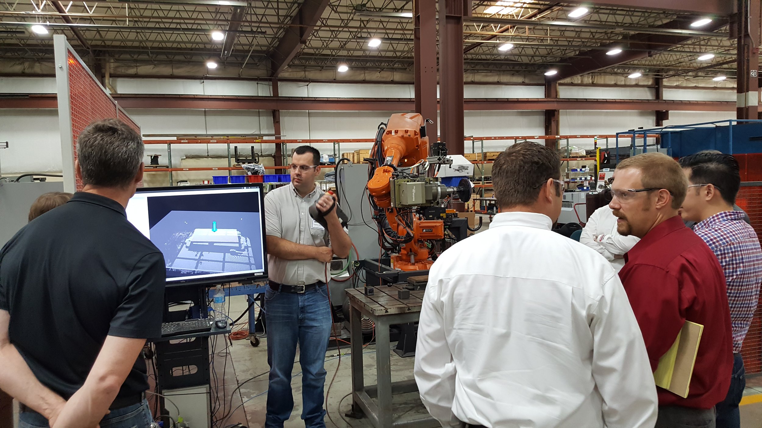
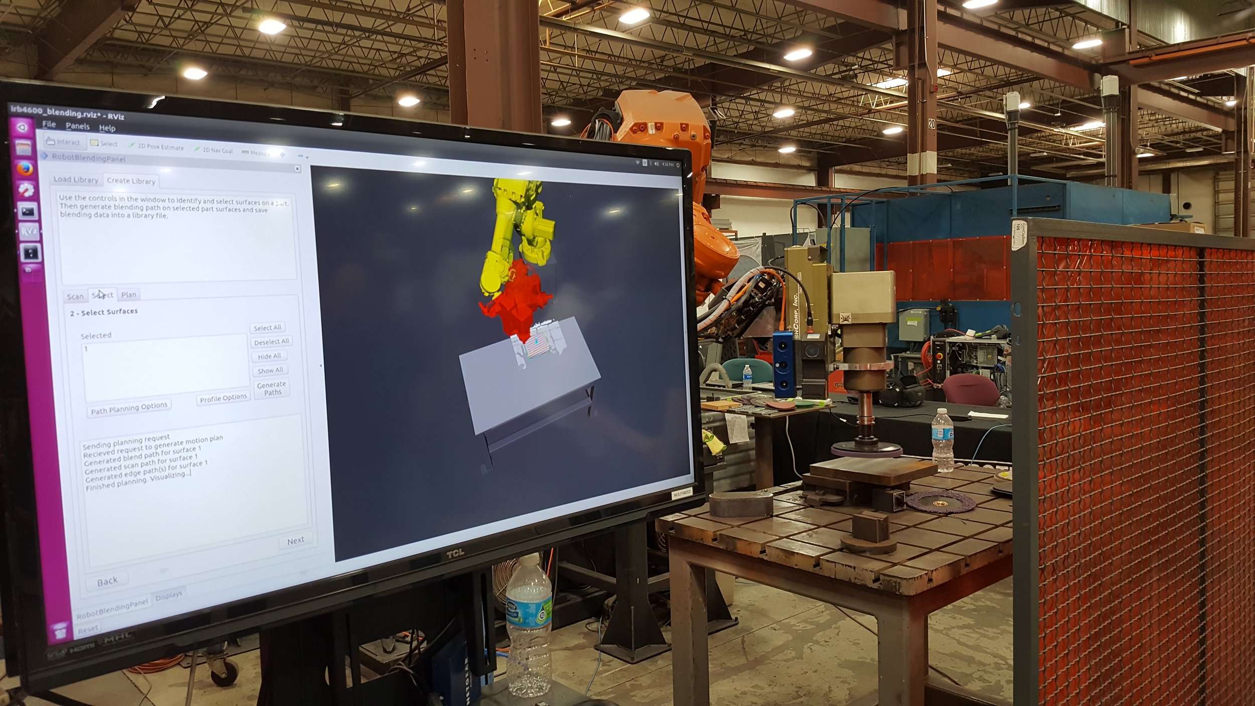
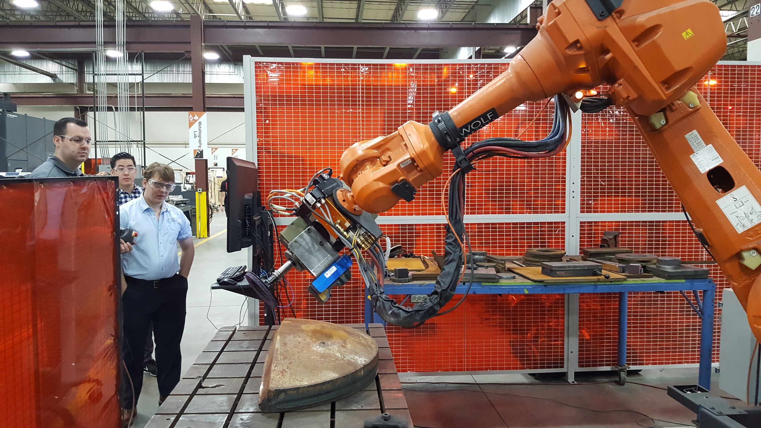
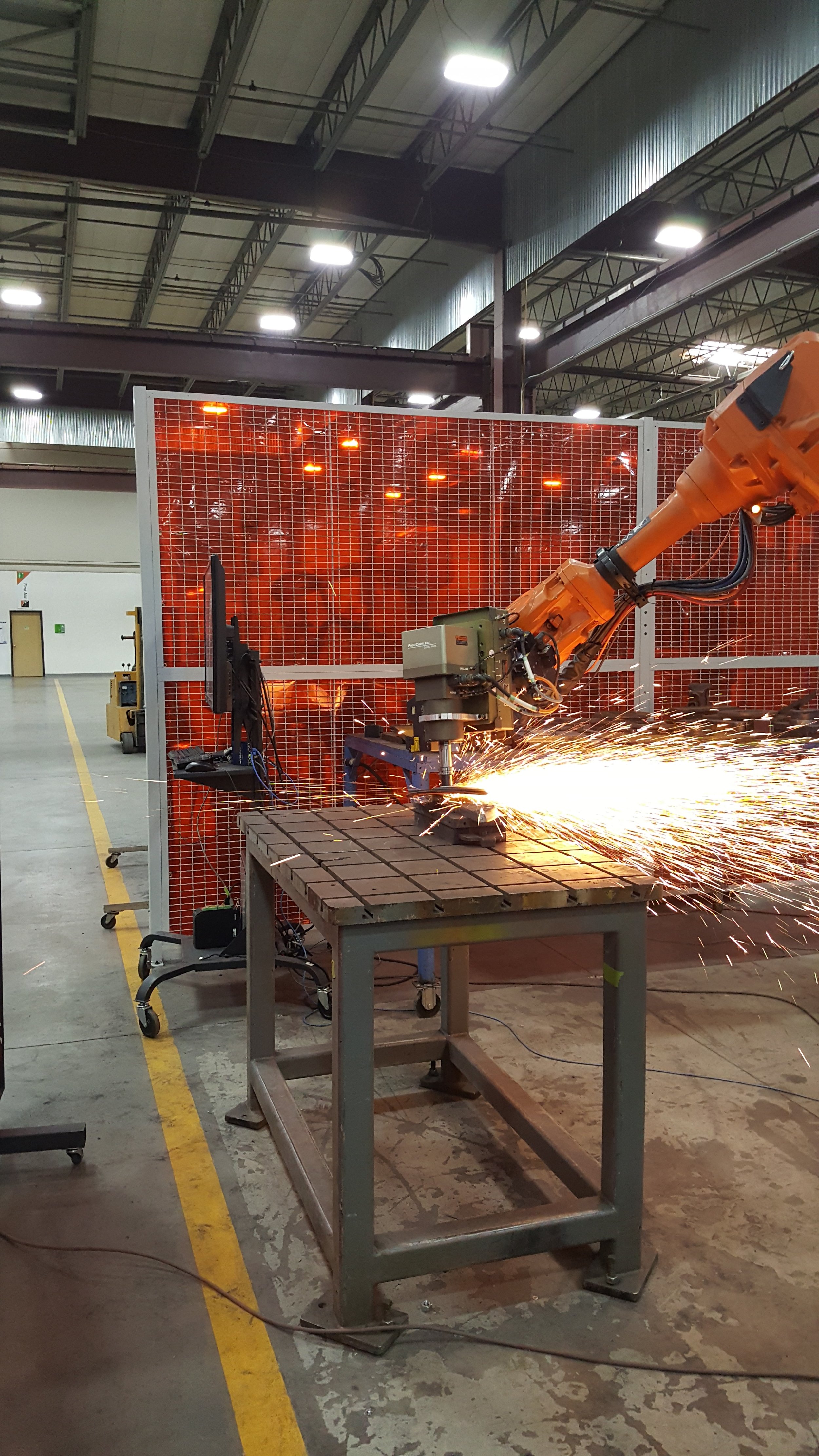
/The Robotic Blending project is the first open source instantiation of what will become a general Scan-N-PlanTM framework (Figure 1). The project has been making steady progress over the past two and a half years.

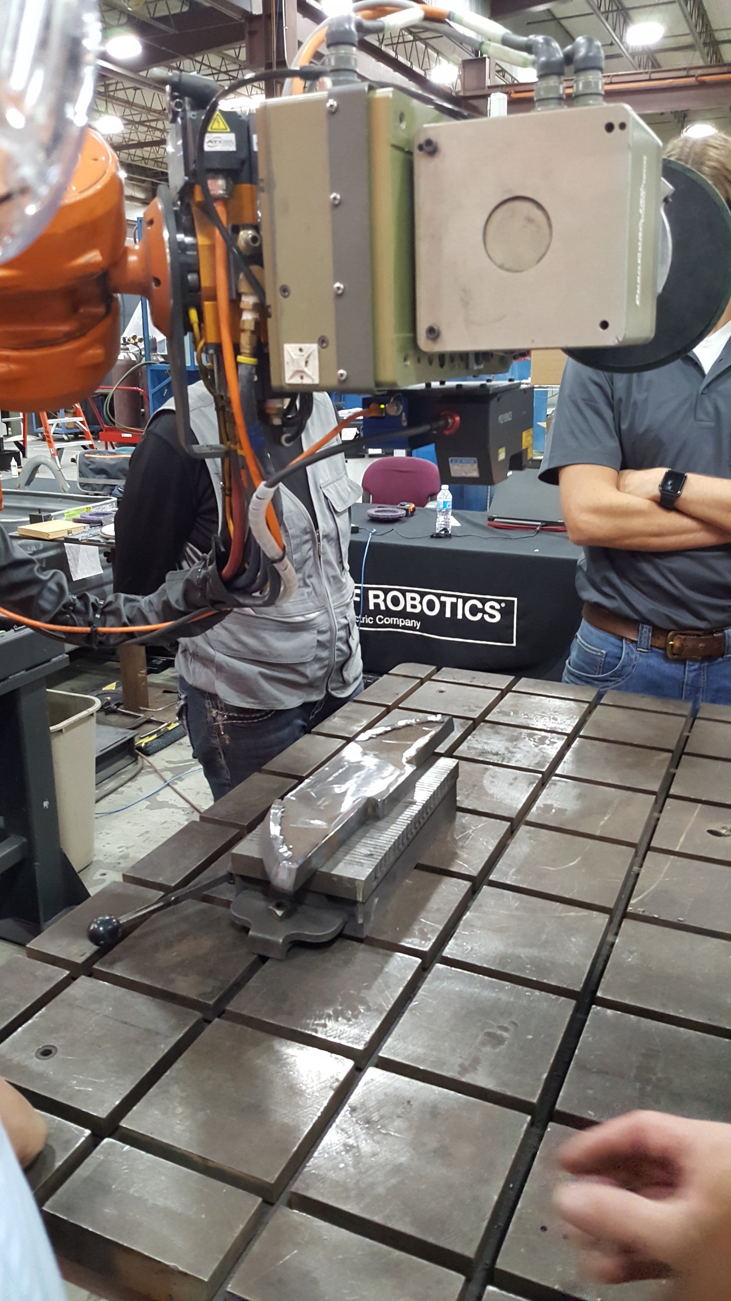
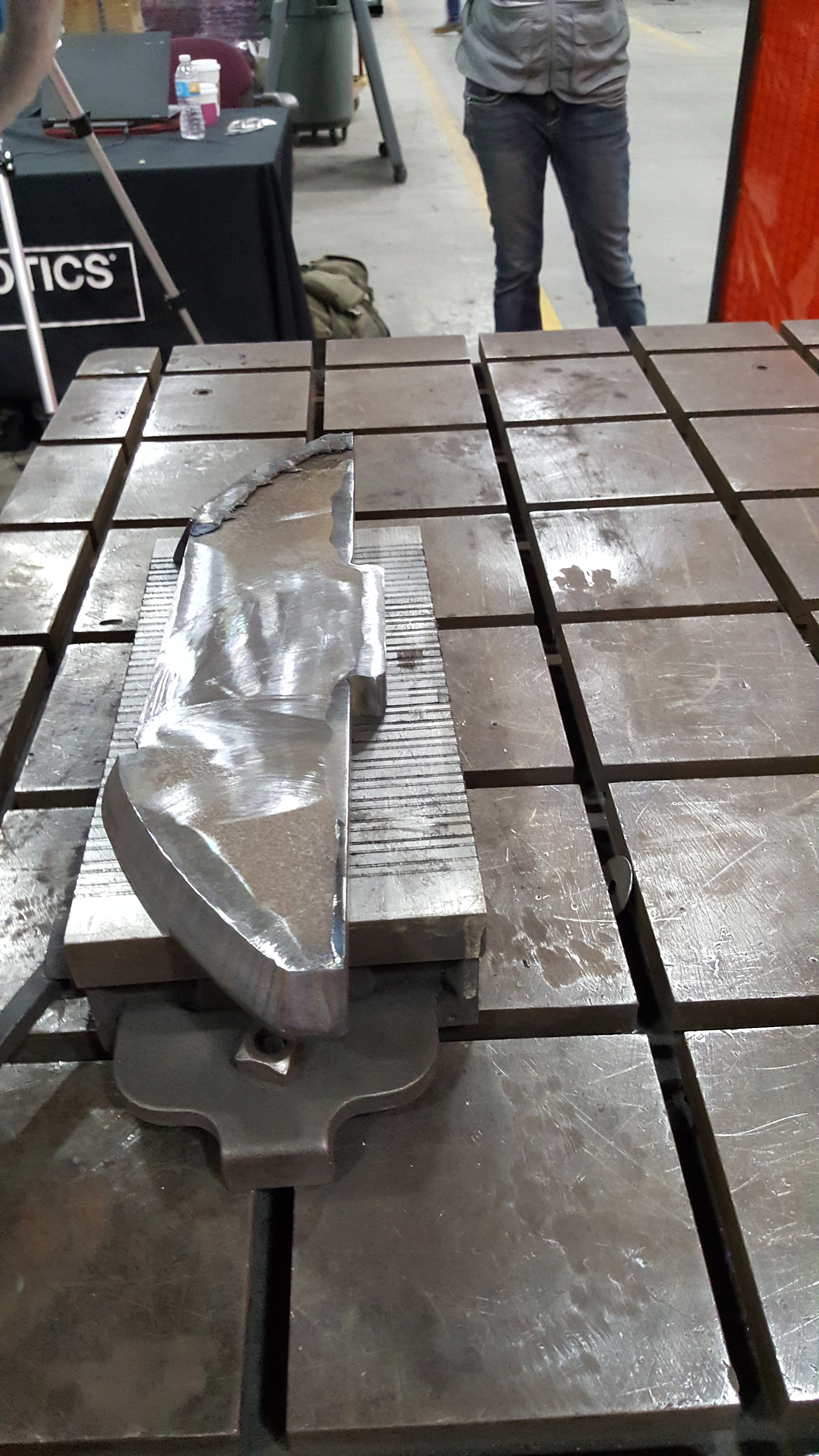
Figure 1. Execution of surface blending of a complex contour part on Wolf Robotics Demonstration Hardware in Fort Collins, CO.
Starting in earnest at the beginning of 2017, Milestone 4 (M4) sought to further the functionality of the technology to incorporate functionality that was of interest to the participating members. These members, 3M, Caterpillar, GKN Aerospace, Wolf Robotics, and the SwRI development team set forth to realize a set of objectives:
- Closed-loop inspection and retouch: Integrating the process planning and quality assurance steps so that parts are finished with a closed, sensor-driven loop.
- More Robust Surface Segmentation: Improving the surface segmentation and planning algorithms to accommodate more complex surfaces found on real parts (continuous surfaces with radius of curvature above a 50 mm threshold, as seen in Figure 1 above)
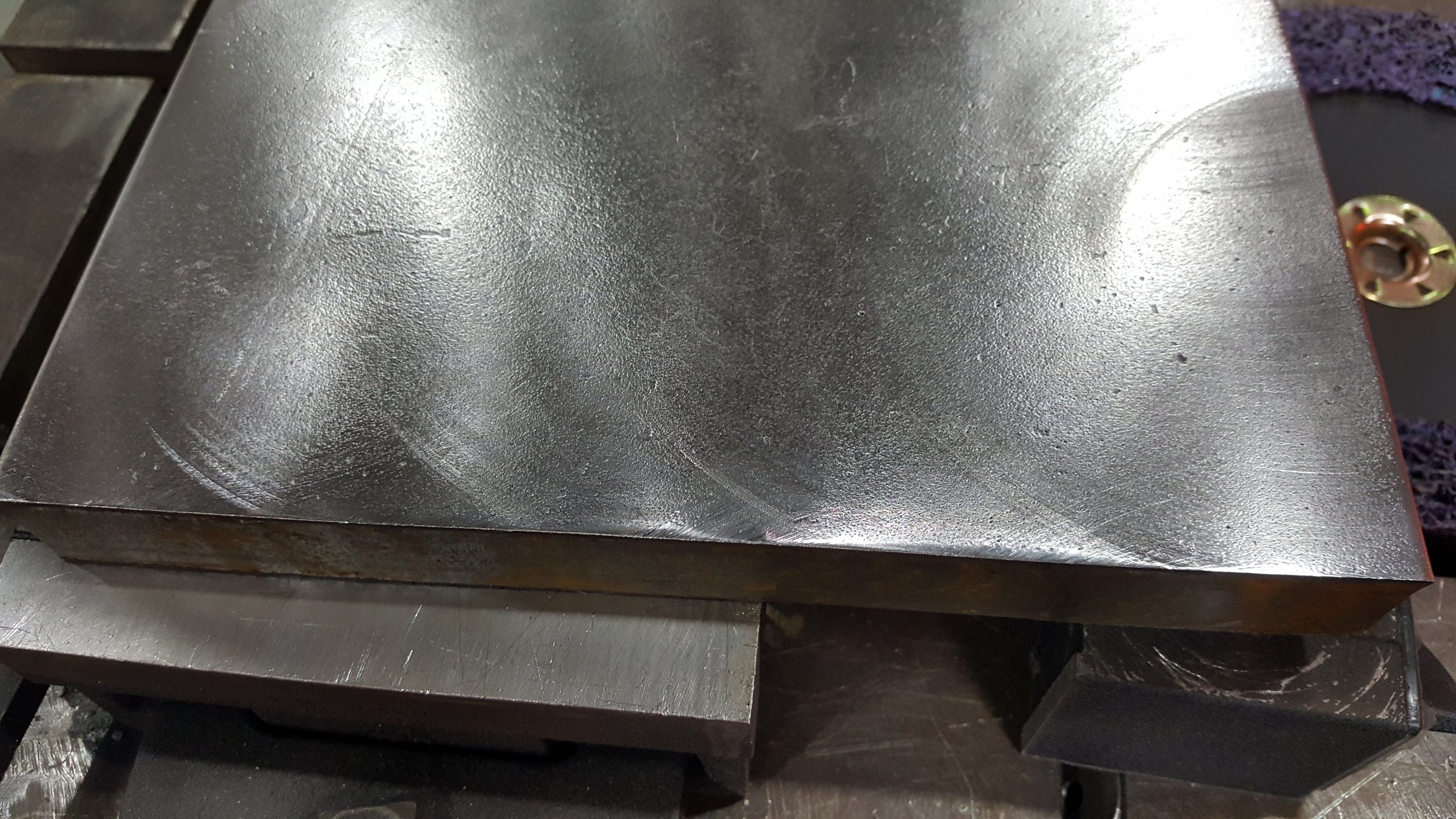
- Blending Process Refinement: Improving the quality of the blending process to produce surface finishes that meet engineering requirements.
- Edge Processing: Processing/chamfering simple 2.5D edges that occur where two surfaces meet.
- Technology Transfer: Meetings, demonstrations, and sponsor sites to support knowledge sharing among project participants and performers.
- Integration and Testing: Demonstration support.
The intent of the demonstration was to review the capability as-developed relative to the processing of provided Caterpillar production parts. Performance was tracked to a provided success criteria that tied to performance metrics that were relevant to the target application.
All parts presented were able to be perceived, meshed, and discrete parts for processing selected. There were difficulties with GUI interaction relative to selection, but these were considered minor.
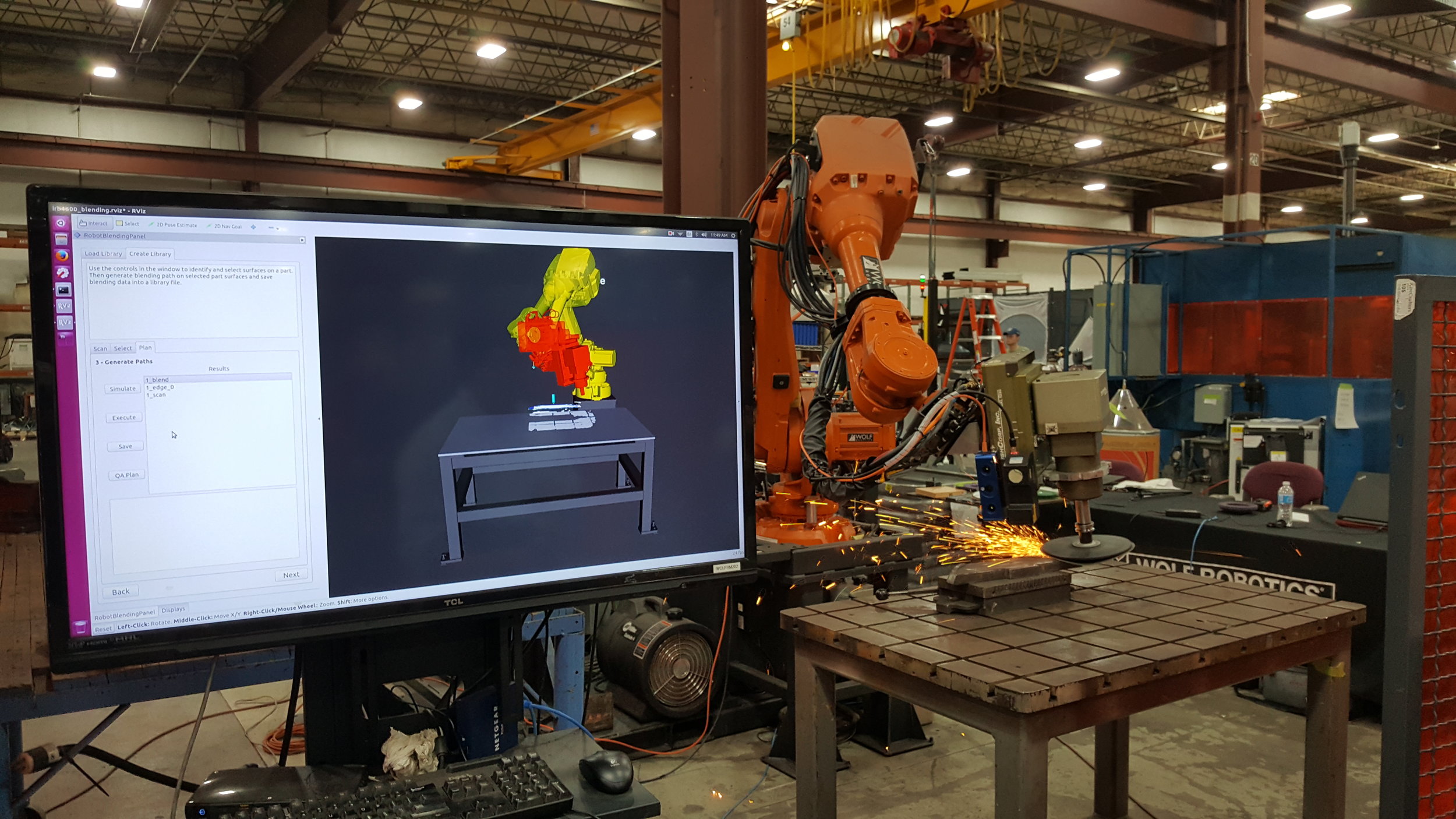
Paths were generated for every part presented that included blending surface paths as well as the edge paths. Every path that was generated was simulated without issue.
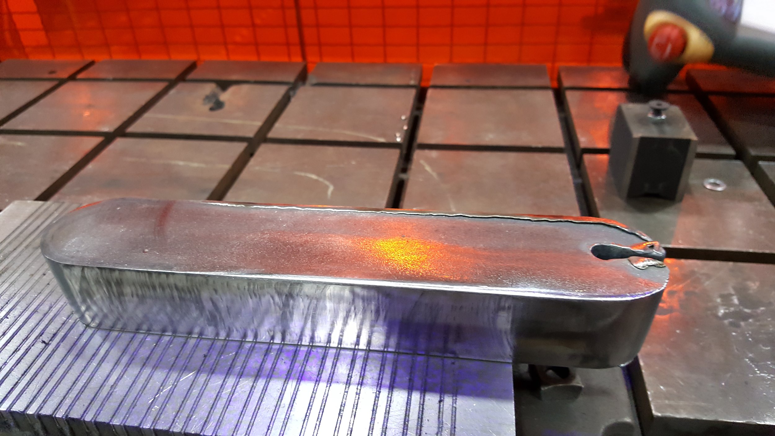
Execution of the blending paths was performed on 100% of presented parts, and a subset of parts for edge processing. There were observed challenges due to the scale of the tools and media relative to the edge and execution of the paths without having issues with either collision or losing contact with the part. This is simply a need for finer calibration techniques for these particular hardware configurations.
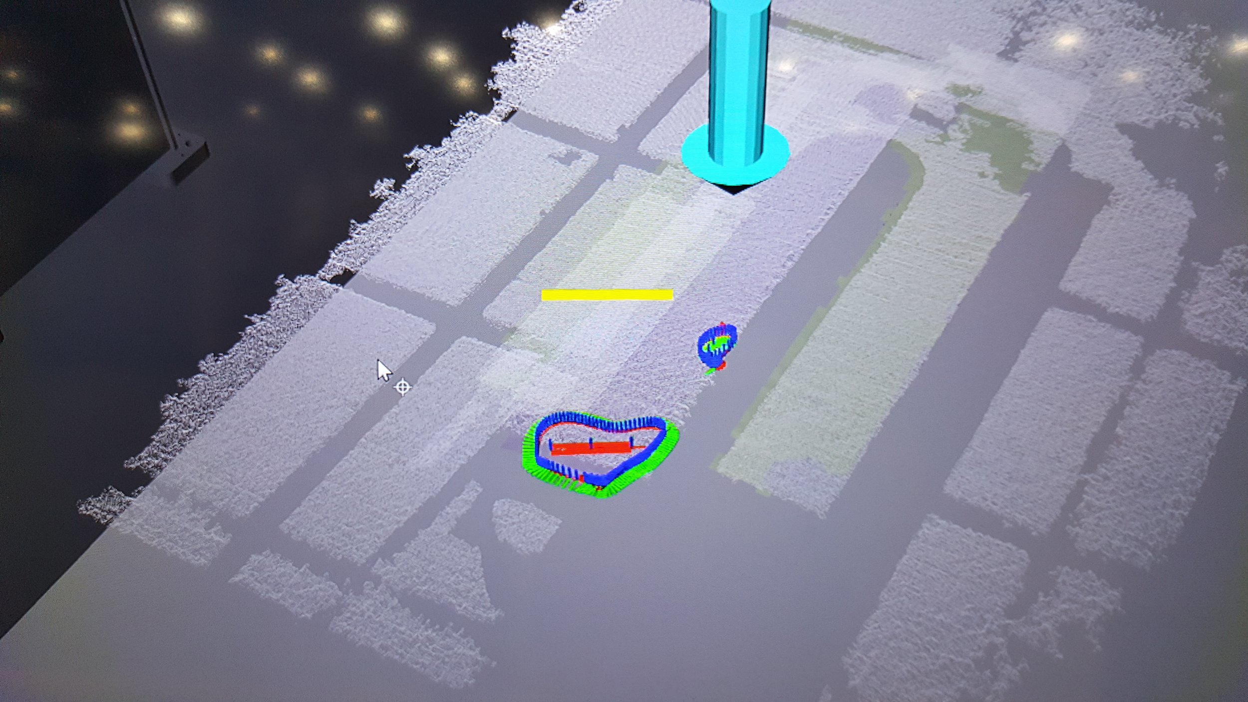
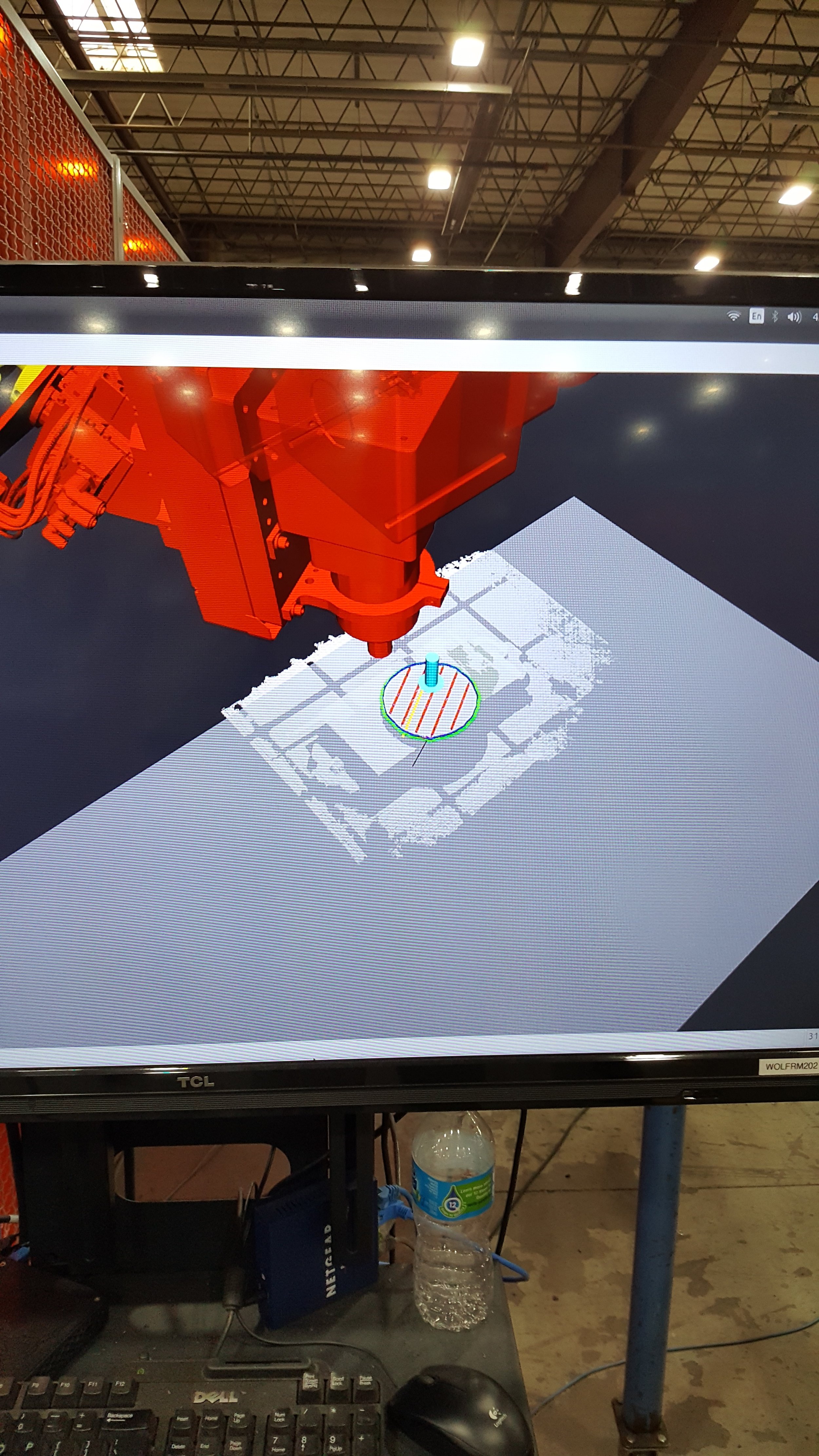
Quality assurance (QA) paths were generated and simulated in all cases. False positives were prevalent and related to scatter/reflectivity, particularly for aggressive media combined with edges/corners on the parts. This is a common issue for laser-based sensors and spectral (shiny) surfaces, particularly along edges. Root cause was identified in detailed views of the scan data showing the scatter that exceeds the acceptance criteria of 0.5 mm.
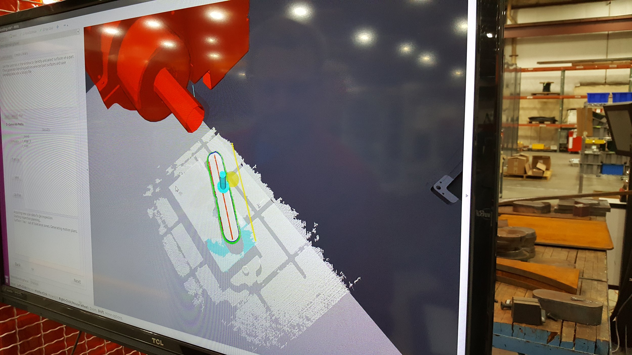
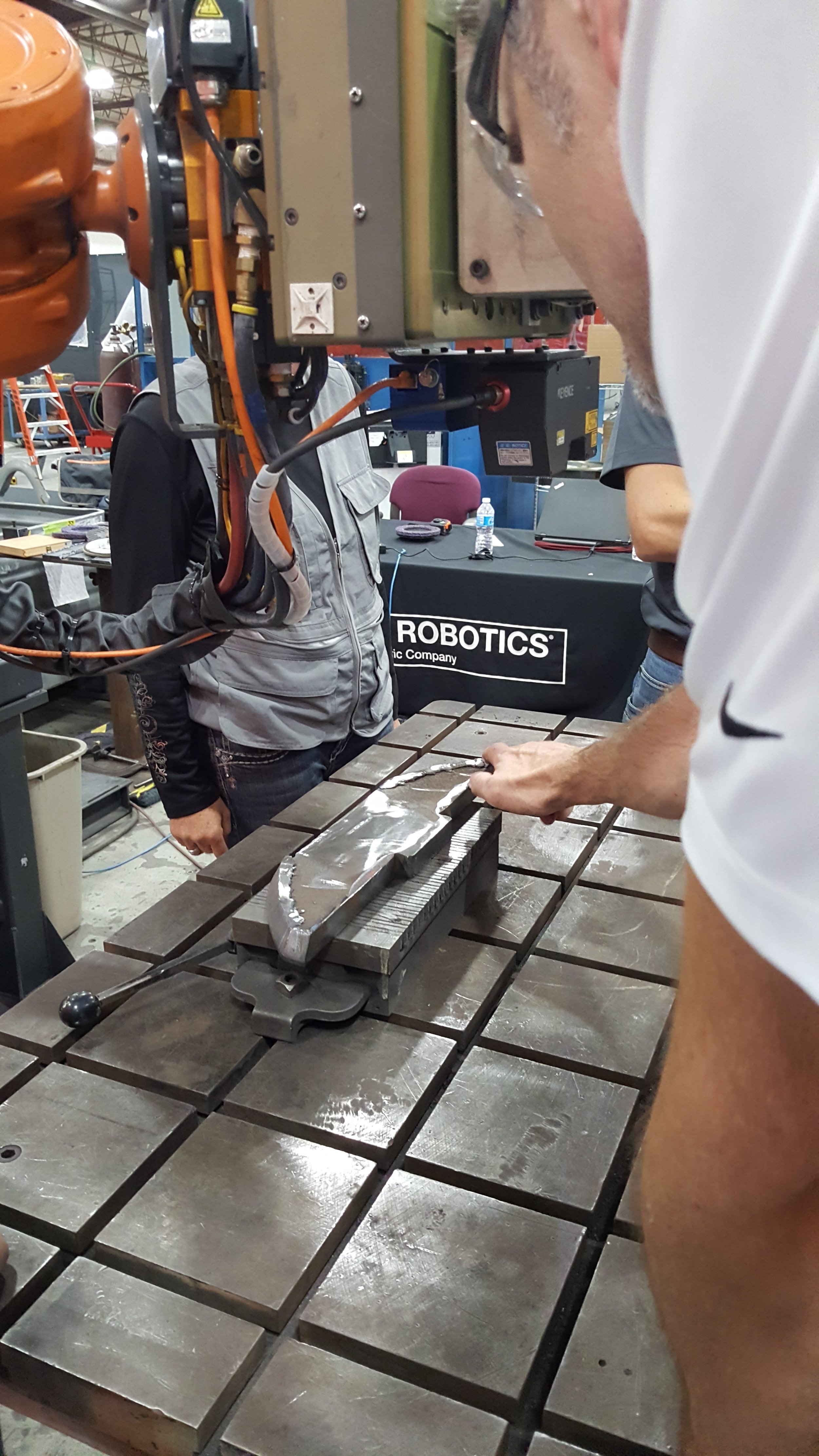
For cases where slag was present to be identified the QA algorithm identified the slag and subsequent path plans were generated, displayed, and able to be simulated and executed, see Figure 2. In cases where there was no remaining slag and the finish was not high spectral the QA passed the part.
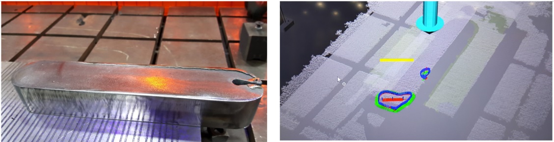
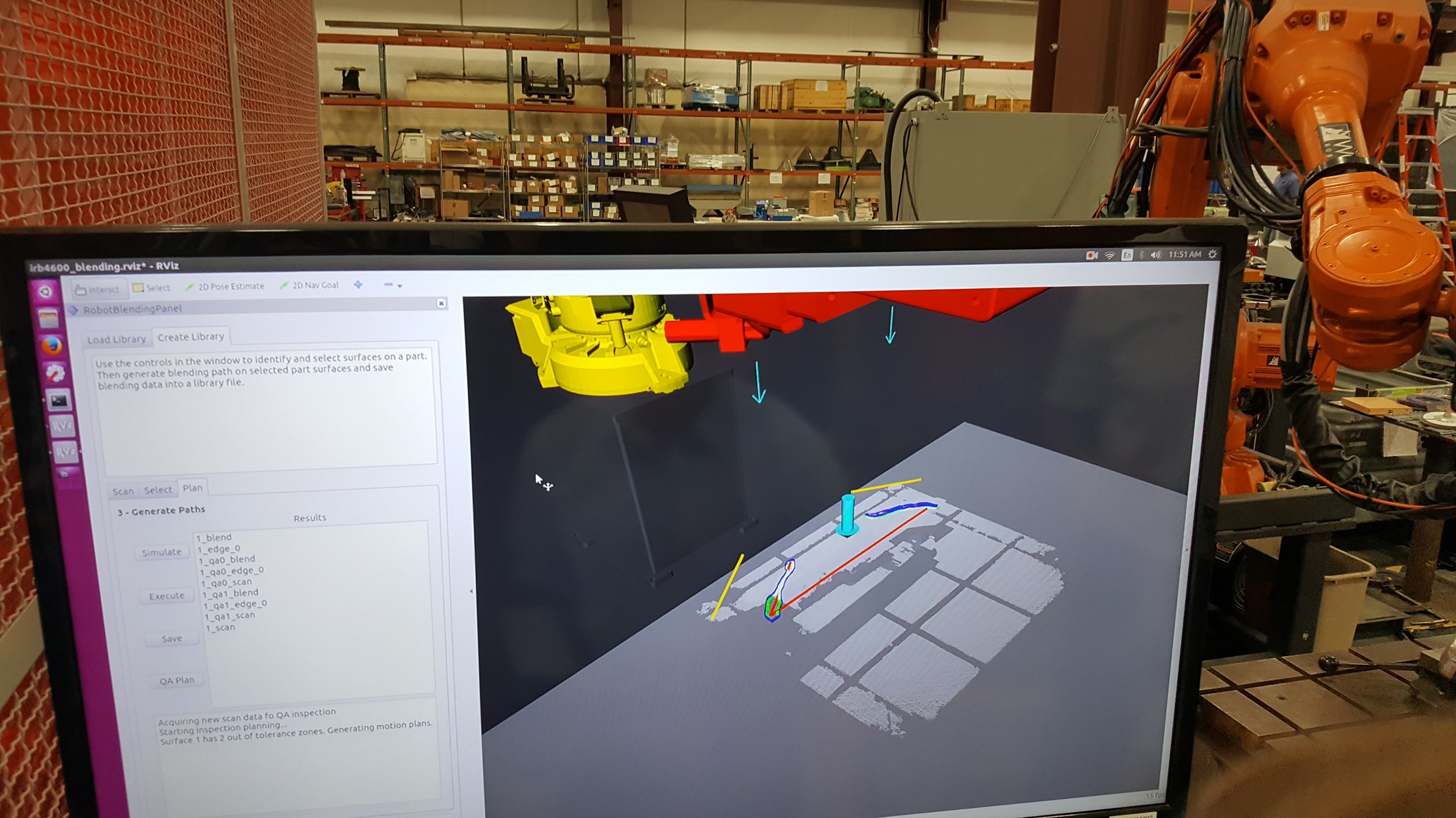
Figure 2. Processed Part and Resultant QA that highlights non-compliant regions for re-processing
Overall, the demonstration was considered a success, and follow on work is in the proposal development phase. The next steps for the team: First, consider establishing two test-sites where follow on development and testing can be performed. Second, evaluate functionality around these elements: work flow, path planning relative to perceived and characterized anomaly or feature, human mark/indication and plan, process refinement considering PushCorp functionality and 3M media, and finally Digital Twin elements to enable consistent performance between the two sites.
Additional information and videos highlighting the current capability will be available soon!
Latest updates to the packages can be found here: https://github.com/ros-industrial-consortium
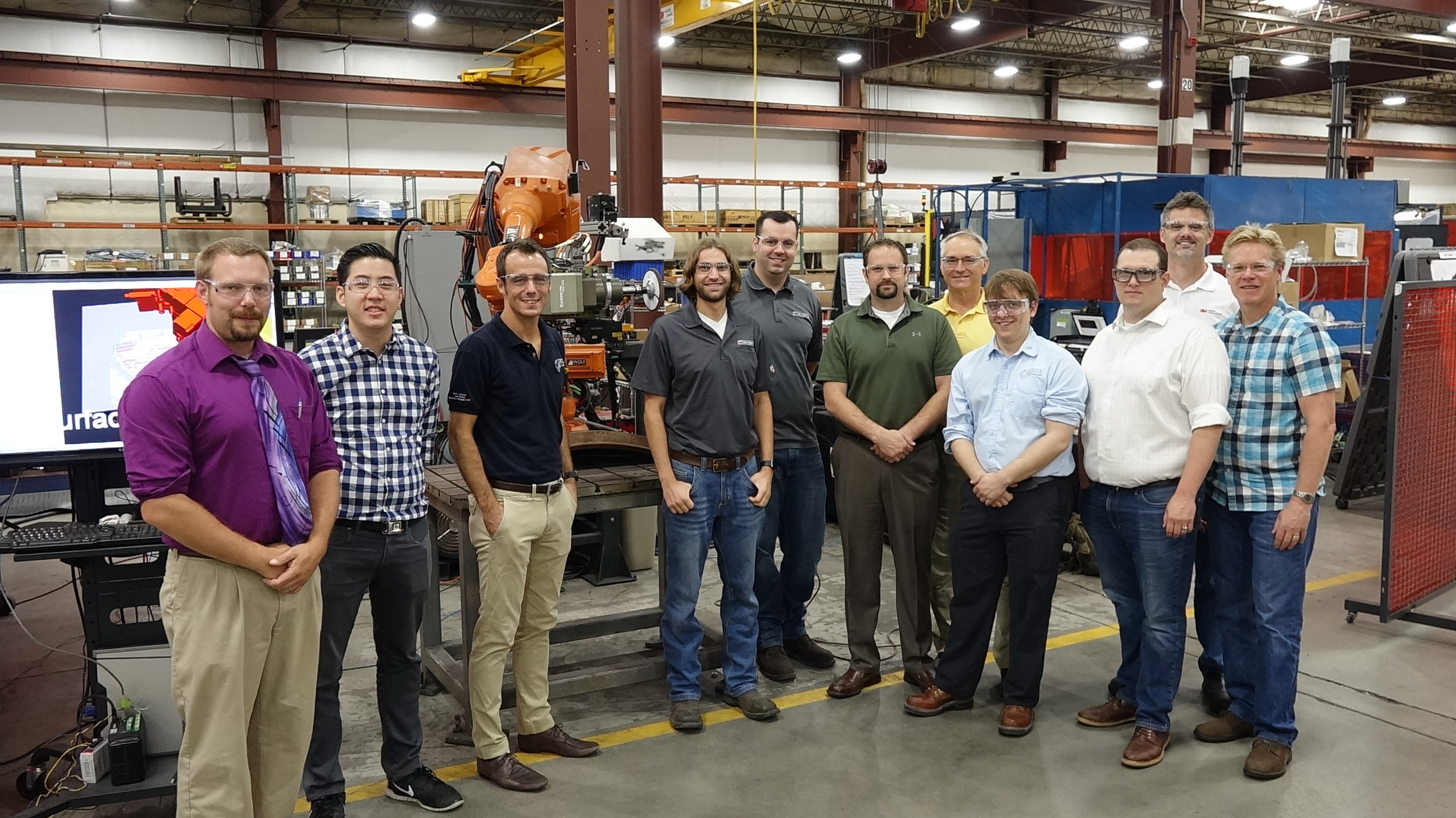
Special thanks to the Robotic Blending M4 team members:
Schoen Schuknecht – 3M
JD Haas – 3M
Leon Adcock – Caterpillar
Prem Chidambaram – Caterpillar
Wajahat Afsar - Caterpillar
Chris Allison – GKN Aerospace
Richard Cheng – GKN Aerospace
Mike McMillen – PushCorp
Jonathan Meyer – SwRI
Austin Deric - SwRI
Alex Goins - SwRI
Lance Guyman – Wolf Robotics
Jason Flamm – Wolf Robotics
Zach Bennett – Wolf Robotics
Nephan Dawson – Wolf Robotics