Open Source Improvements from Recently Completed Robotic Blending M5
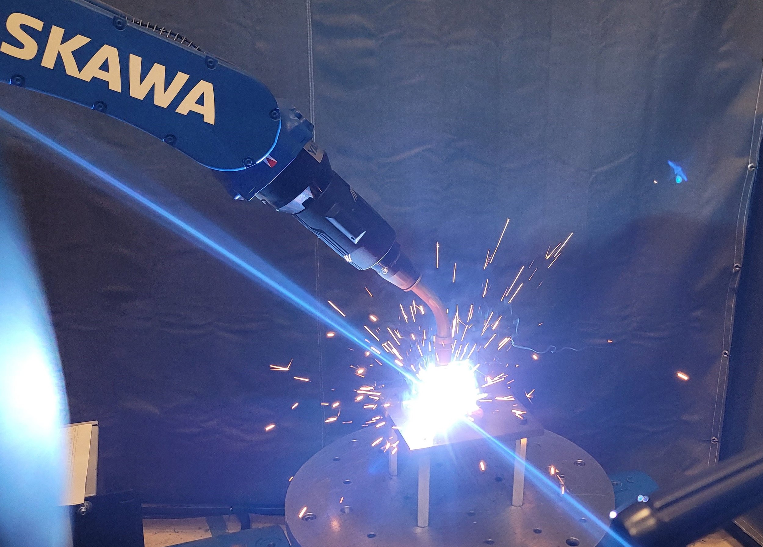
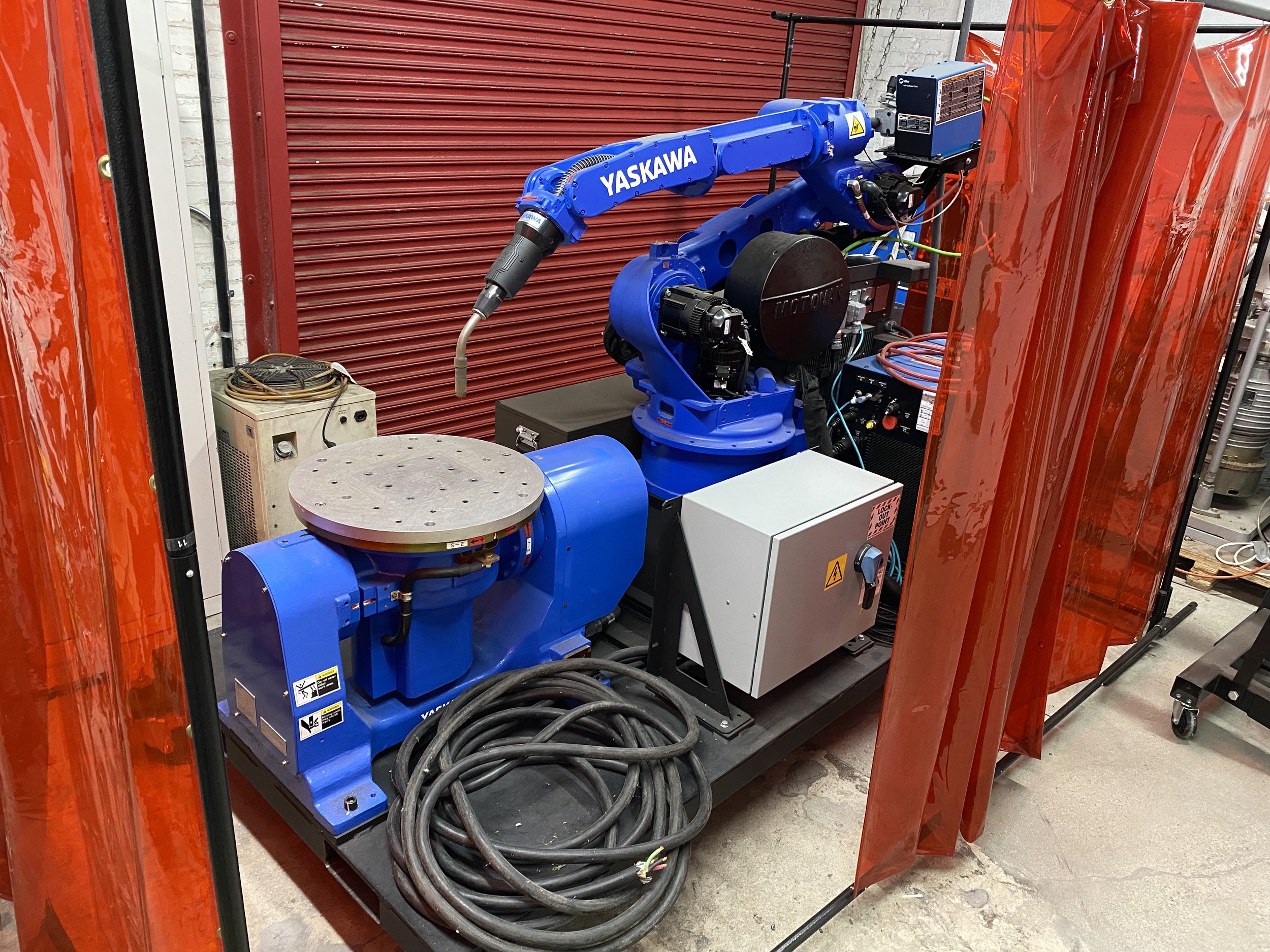
/A Focused Technical Project (FTP), championed by the Steel Founders’ Society of America (SFSA), sponsored by the DLA-Troop Support, Philadelphia, PA, and the Defense Logistics Agency Information Operations, J68, Research & Development, Ft. Belvoir, VA, within the ROS-Industrial Consortium (RIC), has recently completed the Focused Technical Project (FTP) Robotic Blending Milestone 5. The team included RIC team members consisting of Yaskawa America, PushCorp and Southwest Research Institute, along with SFSA member university, Iowa State University. This work culminated in a deployed system at a SFSA member foundry site.
The project built on the prior Robotic Blending Milestone 4, which demonstrated high-mix material surface finishing and edge processing of arbitrarily shaped and contouring parts, largely targeting piece-parts to be welded. This work sought to extend that work, adding new features and incorporating additional SFSA funded work to realize human in the loop high-mix casting finishing for foundry operations.
During the development process, we have contributed the following improvements to the foundational Scan-N-Plan framework that served as a starting point for the FTP. This framework is maintained as a workshop repository within the RIC GitHub repository and is used in whole or in parts for developer instruction in ROS 2 for industrial robotics.
Scan-N-Plan Updates
ROS 2 Control:
We have added ros2_control code to the Scan-N-Plan example implementations to preview the robot’s motion during a simulated motion execution.
Constant TCP Velocity Time Parameterization:
We have added a time parameterization algorithm for maintaining constant TCP speed during motion planning. The approach works by first calculating forward kinematics at each trajectory waypoint to get the pose of the TCP. Then, we create a line path between adjacent TCP poses and parameterize the line with a trapezoidal velocity profile. The joint velocity and acceleration at each waypoint are computed given the TCP Cartesian velocity and acceleration. These obtained velocities and accelerations are then validated to be within the limits of the robot.
Docker Images:
To make the deployment and development of Scan-N-Plan more efficient and standardized, we have created Docker images for ROS 2 Foxy, Humble, and Rolling that can be found here.
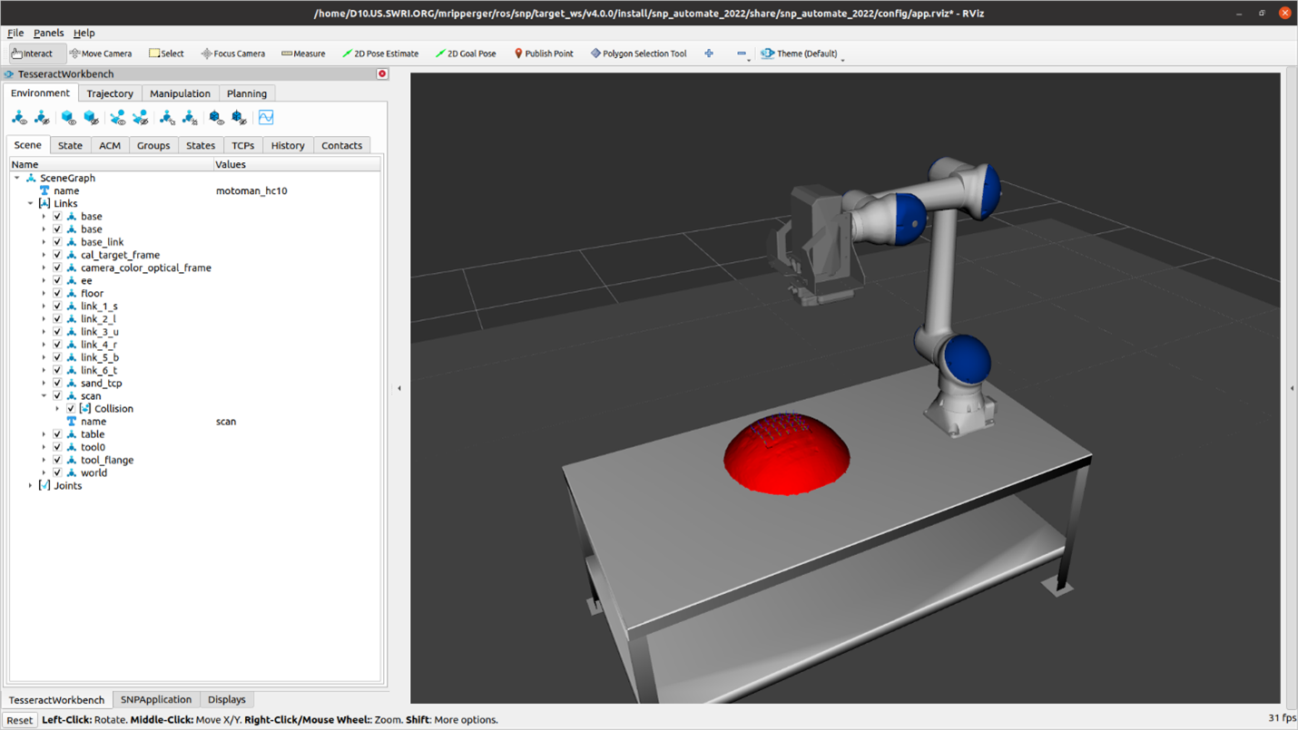
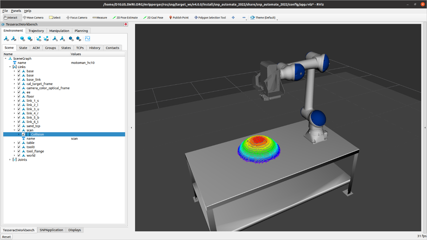
Selectable Representation for Collision Object:
In addition to the default behavior of converting the scan mesh into a convex hull, the collision object can now be represented as a detailed mesh or as an octree.
Default behavior: Converts the scan mesh into a convex hull. This generally results in the fastest motion plans, especially with TrajOpt, but can be too conservative and may cause motion planning failures if the scan object is not actually convex or nearly convex.

Convex Hull Representation of Collision Object
Mesh: Represents the collision object as the exact “detailed” mesh represented by the mesh file. With the contact test type CLOSEST for TrajOpt, this representation results in a somewhat slower planning time than convex_mesh, but not significantly longer.
Mesh Representation of Collision Object
Octree: Represents the collision object as an octree comprised of spheres with a diameter specified by the octree_resolution parameter. With the contact test type CLOSEST for TrajOpt, this representation results in slightly faster planning times than mesh but slower than convex_mesh.
Octree Representation of Collision Object
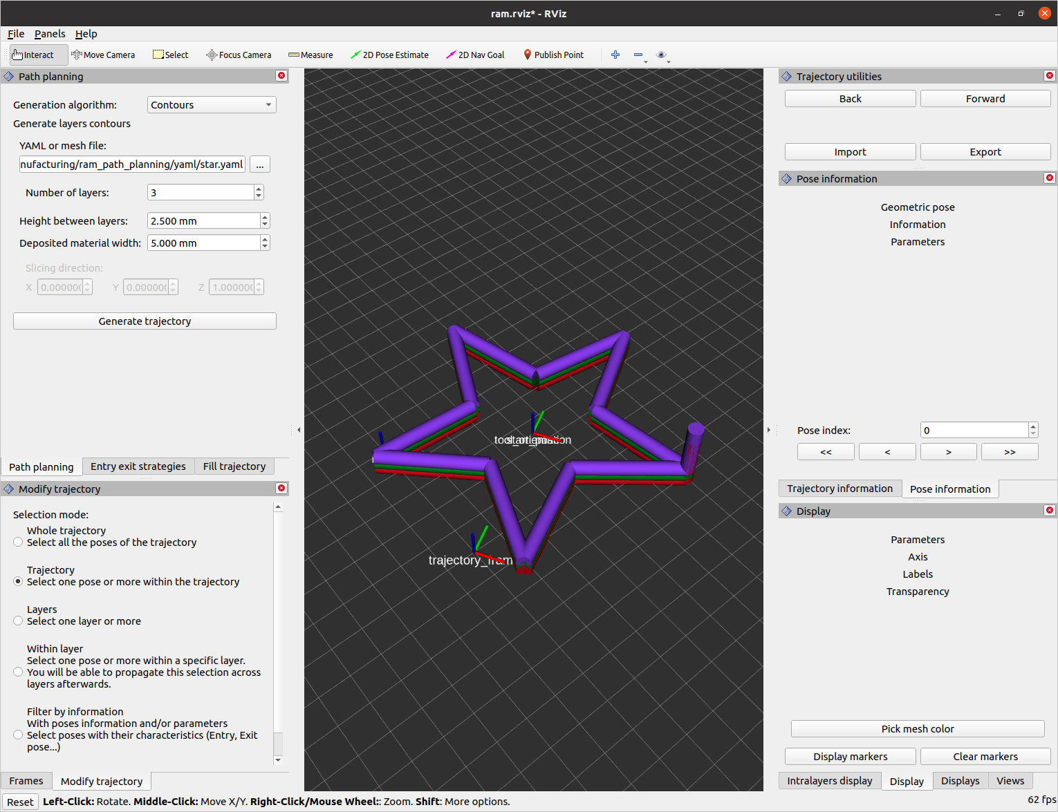
Simplified Raster Planner

Simplified Raster Planner Widget
The parameters exposed in the raster planner GUI widget were modified to only show commonly tuned parameters during raster planning such as rotation offset (degrees), point spacing, line spacing, minimum segment length. This declutters the raster planner to improve usability.
Python Scanning and Execution Nodes
For ease of development and debugging during deployment efforts, we have converted the mesh reconstruction and motion execution simulator nodes from C++ to Python.
Service for Generating Scan Motion Plans
A separate service for generating scan motion plans has been made as an intermediate step to support creating dynamic scan trajectories in the future. This service will be called to create scan trajectory patterns that originate from a specified starting location.
Behavior Tree and Reactive GUI
The custom application back-end logic has been replaced with a behavior tree to improve workflow modularity and customizability. The behavior tree can change the GUI appearance based on the current behavior executed. Widgets are exposed and hidden during the workflow to guide the user’s focus to actions and settings relevant to the process at hand. A progress bar and preview motion bar have been made more accessible to inform the user where they are in the process.
Noether Updates
Tool path and Mesh Visualization Tool

Mesh/Tool path Viewer Widget
When developing and debugging tool path and mesh modifiers, it is helpful to visualize the original tool path, the modified tool path, the original mesh, and the modified mesh. Previously, there was no way to view the unmodified sub-mesh after applying a mesh modifier.
We have added a widget in the Noether application to toggle the view of the mesh and tool path VTK objects. We replaced the concatenated mesh viewer using a vtkAssembly and using vtkSmartPointers instead of using raw pointers for internal objects.

From Left to Right: Modified Tool path and Modified Mesh, Modified Tool path and Original Mesh, Original Tool path and Original Mesh, Tool path Hidden and Modified Mesh
Approach and Departure Tool Paths
To better stay within selected regions during processing, we added linear approach and departure tool paths (see below for the linear approach tool path). A modified version of these tool paths (circular approach/departure) creates an approach/departure curve of specified radius.

Linear approach tool path modifier
Plane Projection Mesh Modifier
We added a mesh modifier that fits a plane to the input mesh using random sample consensus and projects the inlier points onto the plane. This modifier prevents tool paths from being generated on an unintended inner or outer surface near the edge of a complex part, where the desired processing surface should be flat.
We hope developers and those interested in experimenting with ROS 2 for their industrial robotics application development have found this resource helpful. If you have questions, comments, or have observed an issue, please do not hesitate to either engage with the ROS-Industrial community or leave an issue over at the GitHub repository.
Thanks to Michael Ripperger, ROS-I Consortium Americas Tech Lead, SwRI Sr. Research Engineer, for his contributions to the Scan-N-Plan Workshop and the FTP program and this blog post.